I need to order an ALM and a couple of injectors. Rob is after some stuff as well. If anyone else wants to order some Ecotrons stuff shortly let me know and we can combine freight. Otherwise it's $50+- just for freight

 Bucket Racer/Crasher

I need to order an ALM and a couple of injectors. Rob is after some stuff as well. If anyone else wants to order some Ecotrons stuff shortly let me know and we can combine freight. Otherwise it's $50+- just for freight
No8 Wire Extraordinaire

Have you used YouShop? Works well.Originally Posted by speedpro

Don't you look at my accountant.
He's the only one I've got.
Forum whore
Hi Speedpro, this is what I need
Two of these 128g injectors
And two lengths (1m??) each of the blue and clear fuel line that comes in the kit and one 25l pump.
Forum whore
.
Posted so that those who want to try their hand at 2T EFI and Frits 24/7 concept can know their ambition is a realistic possibility.
There are a lot of good EFI ECU's around and Ecotrons sells inexpensive kits and parts, they are worth a look.
Frits has posted some pictures of a working 24/7 setup.
EFI Kawasaki BigHorn running transfer port injection and E85. Runs to 8,000 rpm
Some more Youtube clips of transfer port injected 2T's
http://youtu.be/eleqBGvOM4M
http://youtu.be/hOGZ5llowoU
http://youtu.be/1YG9ko8-Nwk
http://youtu.be/UEQli7nuak4
GerbilGronk is worth a Youtube search.
I have been working on a EFI transfer port injection system of my own but trying to take the concept to 12,500rpm.
I am finding transfer port injection above 9,000rpm is very difficult and I need to find another way to get to 12,500+rpm.
Below is an example of 15,000 rpm Inlet Port Injection.
Larrys post has a few pictures of the BRC fuel injected BRC throttle bodies. More of BRC can be seen here:- http://brceng.com/brc-motorsports/
Video clip of a Inlet Port injected 15,000rpm 2T in action on the dyno.
Forum whore
Attachment 307219Attachment 307220Attachment 307221
Well tonight's effort was a total bust, the two injectors send out such a cloud that it wets out on the bellmouth and dribbles down into the plenum which totally negates the reason for having injectors in the first place. Ie to stop fuel pooling in the plenum.
I can see the advantage of having the injectors behind the throttle slide like they have on the BRC engine. Gave up for the night after the EFI filled the crankcase with raw fuel.
Neels sent me some very informative links.
http://www.sandia.gov/ecn/gasolineSprayCombustion.php
http://www.cmt.upv.es/ECN.aspx
Neels also suggested I take a closer look at what happens at an injector, things like the "liquid length" and atomization and finally evaporation. Also the effect of impinging on a wall at what stage of the plume development.
Forum whore
Ok so I have starting to work it out.
Attachment 307244
It was a bit hard but finally ... Success .....
I have been struggling with detto and running out of injection time trying to squirt in enough fuel to stop it.
In the end, the issue was all about the piston, which was (only just) tapping the head, not a big problem and I was to lazy to fix it, well tonight I did and the deto has disappeared.
Attachment 307242
I shifted the injectors back to the transfer ports and now with a bit of decent squish clearance the Beast rev's to 12,500rpm plus with injection time to spare.
Attachment 307245
So transfer port injection is a realistic option.
Initially I thought 9,000rpm was going to be the limit for transfer port injection but the Beast is now running to well past 12,000 rpm with the original transfer port injection setup.
Attachment 307243
The injectors swap over at about 7k rpm and the two main injectors still have some injection time left at 12,800 rpm and so it looks like it could go to 13 easy enough.
Ok so now that it works, its time to tune it properly and see if we can better the old carb setup.
Forum whore
Attachment 307334
Alpha-N maps need to be smooth without any peaks or severe troughs between cell steps.
Ecotrons has a function where you can export a map to an Excel spread sheet and use the charting function to help smooth the map data.
Attachment 307335 Attachment 307336
Raw data and the chart showing how rough the data is and the engine ran just as roughly.
Attachment 307337 Attachment 307333
Smoothed data and chart.
No Idea if I have done this right, will get to find out tomorrow, hopefully ....
Forum whore
Ok, I have found the section in the Ecotrons manual where it talks about tuning for the throttle blip.
Attachment 307775
By default it does not work above 3,000rpm, but I can set it higher to suit my engine.
Attachment 307776
From a quick read, the amount of enriching is tied to the predicted load increase as the throttle is opened. I guess its like a smart accelerator pump.
Attachment 307777
You can determine the "Load" from the recorded data.
Attachment 307778
And adjust the map, it looks like a bit of trial and error is required to get it right.
Attachment 307783
There are other adjustments in the advanced calibration file for tuning for the rate of change in the throttle opening (TPS).
All I need to do now is learn how to use it.
Hardcore Biker

Posted TeeZee's work over here to keep all the EFI stuff in one place for future reference. You never know, but a EFI Turbo 2T with CVT transmission may be a future possibility.
Factual Facts are based on real Fact and Universal Truths. Alternative Facts by definition are not based on Truth.
Forum whore
Further Progress on the EFI thing ......
L-Plate Rider
Hi guys and thanks for the info on ecotrons.
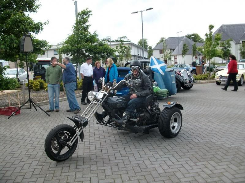
I'm playing around with an ecotrons 250 ninja ecu on my citroen 2cv engine trike and found a lot of usefull info here.
My setup is -
2 cyl 602cc boxer engine, 1 bmw 43mm throttle body with 1 injector. intake manifold splits from the throttle body to each cylinder.
Trigger is from a zephyr 550, four pulses per rev, one long, three short, like the ninja 250 but going clockwise.
As someone mentioned, when bench testing, the injectors appear to fire together in sync. so as long as the ecu will handle a map pulse every revolution then it "should" work. I might have to tell the software it's a single cylinder 301cc 2 stroke.
Great playing with this stuff.
Keep it sunny side up. :-)
Bob in Scotland.
Forum whore
Hi Bob, glad to hear about your project,can you post some photos? they would be interesting to look at. PS you may need to have made a few posts before you can post pictures. Anyway I would love to hear how your project progresses.
L-Plate Rider
Thanks for your interest TZ350.
I'll see if i can post some pics from photobucket........
I had the setup running on the bench last night with the trigger wheel mounted in the lathe and scoped the outputs, only firing one injector and only once per rev, i need it to fire twice per rev but i didnt have any vacuum on the map sensor so that might sort it.
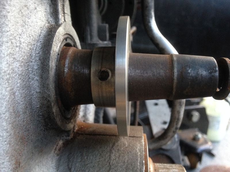
I'm turning up a flange to mount the trigger wheel on the tapered crankshaft, pics will explain it all when i get them up.
L-Plate Rider
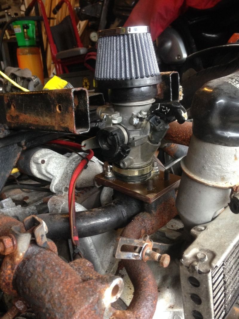
Woohoo... that worked, so here's the bmw f650 throttle body that's been turned down to fit in a 955i inlet rubber and mounted on an insulated plate.
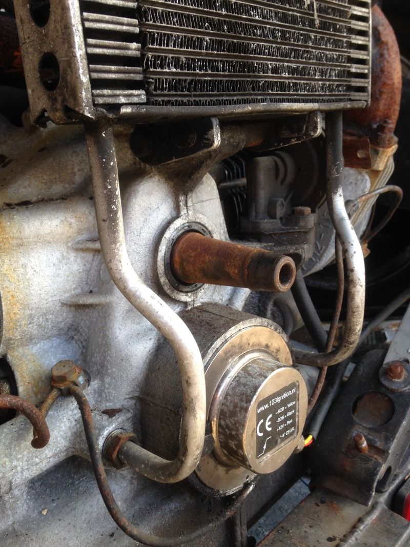
and here's the end of the crankshaft, there's a fan that mounts on the tapered end but there's planty of room for a trigger wheel behind the fan.
here's the aircraft aluminium flange i turned up,
Bucket Racer/Crasher
So, flat twin, 180 degree crank, ignition triggers on the camshaft so assume the cylinders fire alternate revolutions or 360 degrees apart.
If you are using only one injector you will need to fire it every revolution as you have said. I'm assuming from what you have said that you are making your own trigger disc to go on the end of the crank.
If you make a trigger wheel with 6 short teeth and 2 long teeth in a symmetrical pattern - 3,1,3,1, the ECU will think the crank has done 2 revolutions when in fact it has only done one. If you have a MAP fluctuation "every" revolution instead of the Kawasaki's one, the ECU should fire injector one on the 2nd revolution as well. It should be fine to leave injector 2 disconnected but maybe a load wouldn't hurt.
The Ecotrons system uses the MAP to determine which cylinder is firing, instead of using a camshaft mounted "home" trigger.
Since you are doing fabrication I was wondering why you didn't use the Kawasaki/Ecotrons throttle body and just make a trigger wheel to match the required timing. The throttle body flows enough for the engine especially with the volume of the manifold acting as a plenum.
There are currently 1 users browsing this thread. (0 members and 1 guests)
 Posting Permissions

 Reply With Quote
 I think I have shot myself in the foot again.


Bookmarks