Page 2615 of 2629 FirstFirst ... 16152115251525652605261326142615261626172625 ... LastLast
Results 39,211 to 39,225 of 39435

Thread: ESE's works engine tuner

  1. #39211
    Join Date
    2nd November 2023 - 23:26
    Bike
    yamaha rd350A 1974
    Location
    east yorkshire uk
    Posts
    58
    re pipe making i have no where near the experience of some on here but i find i use cad only to draw a straight pipe with all its dimensions and maybe the centreline of a bending header with angles.
    once ive got the angle of change of each section i then use a fantastic free program called cone v1.3
    later versions v2.0 have a time limit and are not free.
    you can input start and end angles and diameters and lengths for your cones and even adjust where the seam is using a box labelled Phi.

    you do have to add on the thickness of your material to the diameters.

    it outputs to its own .con files and also exports the flat pattern projection as a .dxf file which autocad reads and my local laser cutters have no problems with.

    i sound like a salesman.

    i know programs like torqsoft output all the dxf files for you (dunno about other progs like mota or engmod?) but ive got used to this and can output say 15 dxf files for a pipe in half an hour.

  2. #39212
    Join Date
    2nd November 2023 - 23:26
    Bike
    yamaha rd350A 1974
    Location
    east yorkshire uk
    Posts
    58
    Quote Originally Posted by wobbly View Post
    Al , you are making it all way to complicated for a shitbox road bike.
    The skinny pipe has way too steep rear cone angles for a cruiser , and the FOS design is worse , but I guarantee that is overscavenging the hell out of the cylinder due
    to the steep diffusers.
    With the little info I have here is a super simple layout that will work , if the TL is correct from the other two designs.
    The diffuser is simply divided into 2/3 - 1/3 lengths and the belly diameter a guess to get a shallow rear cone to fit easily.
    I have no idea if the 15mm exit is correct for the projected bmep.
    i built this pipe thanks Wobbly and just road tested it now (yet to try different jetting but seems ok) and using video speedo comparison it has the same accel as the thin pipe, but is ever so slightly slower acell than the fat pipe in the top 2 gears. fat pipe with its over rev to 10k can change up back into the power.

    the fat pipe is still the best pipe yet shouldnt work and the rear cones are probably only for ornament?

    all have same tuned length, thin stops revving at 8k, your pipe stops at 9k and the fat revs to 10k. all have exactly the same wobbly duct geometry built into the header.

    i am stuggling to notice patterns of different pipe geometry in relation to on-road performance.

    i am about to build 2 more pipes, one of them is an 80% thinner version of the fat pipe and the other i did take the liberty of tweaking your design by adding a 2 stage header and a 3 part rear cone which starts off shallow then steepens with each cone much like the fat pipe and maybe this initial first shallow rear cone is helping the over rev?

    over rev was something i initially didnt want but have since realised with spaced out gears and only 4 of them it is essential.


    for cruising purposes only all 3 pipes are a success.

  3. #39213
    Join Date
    7th October 2015 - 07:49
    Bike
    honda ns 400
    Location
    Lithuania
    Posts
    476
    Quote Originally Posted by lohring View Post
    I love it. Where can I get one? By the way, I drew a piston ported engine with a C port. Is t better? I have no idea.

    Lohring Miller

    Attachment 354359
    With this nice scheme, maybe intake window can be opened in progressive way. Longest duration at the farthest wall of intake channel and shortest duration near C.
    With more extended intake channel under A, although this will not increase the cross-section of the channel, maybe even longer duration possible without revers flow.

  4. #39214
    Join Date
    6th February 2012 - 08:54
    Bike
    1988 cagiva freccia
    Location
    france
    Posts
    202
    Blog Entries
    1
    "The diffuser is simply divided into 2/3 - 1/3 lengths"


    This is the rule that "Jean Louis Millet" tells us.
    the French exhaust specialist
    Attached Thumbnails Attached Thumbnails Click image for larger version. 

Name:	IMG_20240216_093651.jpg 
Views:	173 
Size:	244.5 KB 
ID:	354363  

  5. #39215
    Join Date
    18th March 2012 - 08:35
    Bike
    Homebuilt chassi, Kawasaki 212cc
    Location
    Sweden
    Posts
    663
    A little movie to get you going this late friday afternoon.
    (i promise, it revs like a mother when i put some load to it)


  6. #39216
    Join Date
    2nd November 2023 - 23:26
    Bike
    yamaha rd350A 1974
    Location
    east yorkshire uk
    Posts
    58
    so now the goalposts have moved in the quest for a perfect cruising pipe cos now it needs a bit of overrev to get me back in the power on changing up.

    im guessing if i made your (wobbly) pipe design diffuser just one angle that would give me more overrev? cos it would be a steeper angle nearer to the header returning the wave quicker hence better at higher rpm

  7. #39217
    Join Date
    2nd November 2023 - 23:26
    Bike
    yamaha rd350A 1974
    Location
    east yorkshire uk
    Posts
    58
    Quote Originally Posted by philou View Post
    "The diffuser is simply divided into 2/3 - 1/3 lengths"


    This is the rule that "Jean Louis Millet" tells us.
    the French exhaust specialist

    is there anywhere i can see some more of his "rules"?


    the pipe that wobbly designed for my purposes demonstrates this percentage within 1 %

    as i now understand the sharpest change of angle in the diffuser is where the amplitude will be highest. so not only is it about percentages but what angles they are and where in the diffusers length they occur.
    nearer to header = higher up the rev range and vice versa.


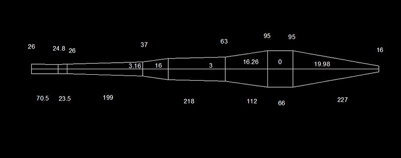
    has anyone ever designed a pipe that has an initial sharp diffuser followed by a very small angle mid maybe even straight? followed by a final sharp angled last difuser section? to try and enhance power at the extremes of the rev range ? in the process not sapping as much energy so there is loads left for the rear cone? as in the pic below.

    the lengths and diameters are wrong but the angles are total and correct

  8. #39218
    Join Date
    7th October 2015 - 07:49
    Bike
    honda ns 400
    Location
    Lithuania
    Posts
    476
    Quote Originally Posted by aljaxon View Post
    is there anywhere i can see some more of his "rules"?


    has anyone ever designed a pipe that has an initial sharp diffuser followed by a very small angle mid maybe even straight? followed by a final sharp angled last difuser section? to try and enhance power at the extremes of the rev range ? in the process not sapping as much energy so there is loads left for the rear cone? as in the pic below.

    the lengths and diameters are wrong but the angles are total and correct
    I'm not sure, maybe it's just a visual trick, but the first ring of the diffuser on YZR 500 2001 looks sharper for eye than usual.
    Attached Thumbnails Attached Thumbnails Click image for larger version. 

Name:	YZR 500 2001 Abe.jpg 
Views:	154 
Size:	808.6 KB 
ID:	354378   Click image for larger version. 

Name:	YZR 500 2001 Checa.jpg 
Views:	113 
Size:	803.9 KB 
ID:	354380  

  9. #39219
    Join Date
    15th December 2022 - 06:58
    Bike
    Tomos BT50
    Location
    Croatia, Virovitica
    Posts
    51
    Quote Originally Posted by aljaxon View Post
    ......................................

    has anyone ever designed a pipe that has an initial sharp diffuser followed by a very small angle mid maybe even straight? followed by a final sharp angled last difuser section? to try and enhance power at the extremes of the rev range ? in the process not sapping as much energy so there is loads left for the rear cone? as in the pic below.

    the lengths and diameters are wrong but the angles are total and correct
    Hi Aljaxon,
    I follow your tests and drawings. According to the description you gave, I adjusted your pipe drawing to LT= 820mm and Dmax = 83mm, for my 50ccm moped with piston-ported intake.
    I compared the simulation and got a red characteristic graph.
    My model is based on the FOS - pipe concept, which I slightly modified and after many attempts got a wider black graph.
    I think that the FOS - concept is better suited for the 50cc class.

    Click image for larger version. 

Name:	TEM15-D603D36C-D30graph.png 
Views:	218 
Size:	68.4 KB 
ID:	354381

  10. #39220
    Join Date
    2nd November 2023 - 23:26
    Bike
    yamaha rd350A 1974
    Location
    east yorkshire uk
    Posts
    58
    good to see that skako. i am using the wobbly duct on all the latest designs ive done and was told that the FOS pipe doesnt work well with that.

    ive got 2 more to build - 1 thats a mod of a pipe that wobbly quickly and kindly designed that im currently testing
    and another thinner version of a fat pipe with belly size 4.8 x ex port area. which shouldnt really work well but its the best pipe ive made out of 5 in the last few months.
    once these are done and tested i might try something similar to that last design with the 3 degree main diffuser cos its easy for me to cut out the existing diffuser on an old pipe and replace it with another diffuser.
    im stuck with the start and end angle but can mess about.

    im only testing the pipes by changing jetting and leaving ignition alone.
    i do fear that by keeping the ignition the same im not realising the full potential of some pipe designs.

    i have video clips for each pipe and can compare them to see real world road performance which i now believe to have more value for my (mickey mouse) purposes than a dyno graph.

    im gonna have a search on here and see what youve been up to skako to see what i can learn

  11. #39221
    Join Date
    6th February 2012 - 08:54
    Bike
    1988 cagiva freccia
    Location
    france
    Posts
    202
    Blog Entries
    1
    Quote Originally Posted by aljaxon View Post
    is there anywhere i can see some more of his "rules"?

    he is dead.
    it was paid internships with him mainly focused on construction

    generally, the leak tube for 50cc is 16 mm

  12. #39222
    Join Date
    15th December 2022 - 06:58
    Bike
    Tomos BT50
    Location
    Croatia, Virovitica
    Posts
    51
    Hi,
    I tried to adapt the wobbly pipe, #39123, designed for aljaxon to LT= 825mm for my model.
    I adjusted the pipe to have the same inlet for a better comparison.
    I tried to keep the angles and dimension ratios as much as possible.
    I was interested in how close I am to the characteristics of the wobbly pipe, which can be seen on the graph.
    I assume that aljaxon could expect a similar characteristic on his moped at lower RPM.

    Click image for larger version. 

Name:	TEM15-D603D36D-D30WobblyAljaxson.png 
Views:	194 
Size:	73.0 KB 
ID:	354396

  13. #39223
    Join Date
    6th February 2012 - 08:54
    Bike
    1988 cagiva freccia
    Location
    france
    Posts
    202
    Blog Entries
    1
    skako, you can test this one ?

    ษdit : 13 mm leak tube for 50cc o_0 it will break. the oil film in the cylinder will burn on the exhaust side
    Attached Thumbnails Attached Thumbnails Click image for larger version. 

Name:	ninja_10.jpg 
Views:	89 
Size:	218.5 KB 
ID:	354397  

  14. #39224
    Join Date
    20th April 2011 - 08:45
    Bike
    none
    Location
    Raalte, Netherlands
    Posts
    3,342
    Quote Originally Posted by skako View Post
    Hi,
    I tried to adapt the wobbly pipe, #39123, designed for aljaxon to LT= 825mm for my model.
    I adjusted the pipe to have the same inlet for a better comparison.
    I tried to keep the angles and dimension ratios as much as possible.
    I was interested in how close I am to the characteristics of the wobbly pipe, which can be seen on the graph.
    I assume that aljaxon could expect a similar characteristic on his moped at lower RPM.
    Click image for larger version. 

Name:	TEM15-D603D36D-D30WobblyAljaxson.png 
Views:	194 
Size:	73.0 KB 
ID:	354396
    Skako, the 13 mm ุ restrictor in your pipe drawing corresponds neatly to the 13 crankshaft-kW (17,43 crankshaft-HP) in your power curve.
    But as soon as the engine starts making more power than that, 13 mm ุ will be dangerously small.
    As a rule of thumb the restrictor diameter should be at least 3,1* the square root of the crankshaft-HP. Also notice the comment in the FOS exhaust concept below.Click image for larger version. 

Name:	FOS exhaust concept.png 
Views:	62 
Size:	48.4 KB 
ID:	354398

  15. #39225
    Join Date
    2nd November 2023 - 23:26
    Bike
    yamaha rd350A 1974
    Location
    east yorkshire uk
    Posts
    58
    Quote Originally Posted by philou View Post
    he is dead.
    it was paid internships with him mainly focused on construction

    generally, the leak tube for 50cc is 16 mm
    shame.
    i use a 16mm stinger outlet on my aircooled 74cc kit and my ex port area is 25mm diameter equivalent and i find i do get quite hot under sustained high load.
    i might try 17mm to see if temps come down.

Thread Information

Users Browsing this Thread

There are currently 474 users browsing this thread. (0 members and 474 guests)

Posting Permissions

  • You may not post new threads
  • You may not post replies
  • You may not post attachments
  • You may not edit your posts
  •