Page 610 of 2703 FirstFirst ... 11051056060060860961061161262066071011101610 ... LastLast
Results 9,136 to 9,150 of 40535

Thread: ESE's works engine tuner

  1. #9136
    Join Date
    2nd April 2012 - 00:54
    Bike
    Aprilia GP 125 & 250, 91 & 92 models
    Location
    Australia
    Posts
    94
    Frits you posted the details for the 102 pipe and there was a mention of a 106 pipe, would you share that with us and if it's not to much trouble would you share your knowledge with what performance differences were noted between these two models

    With regards to the spark plug posted elsewhere, I have seen the ground separate from the body with that plug

  2. #9137
    Join Date
    20th April 2011 - 08:45
    Bike
    none
    Location
    Raalte, Netherlands
    Posts
    3,396
    Quote Originally Posted by RAW View Post
    Frits you posted the details for the 102 pipe and there was a mention of a 106 pipe, would you share that with us and if it's not to much trouble would you share your knowledge with what performance differences were noted between these two models/
    The only difference is the end cone restrictor diameter: it's 23.3 mm for the 102 and 23.0 mm for the 106 (or the other way around; I can never remember which is which). One was for the 125 cc and the other was for the 250. As the 125 is on full song for a much greater part of the track than the 250, the restrictor difference should compensate for the EGT build-up. Personally I would never go below 23.3 mm with that kind of horsepower.

    With regards to the spark plug posted elsewhere, I have seen the ground separate from the body with that plug
    Thanks for the warning. Aprilia switched from NGK to Denso because parts of the isolator fell into the cylinder. Now they have switched to Superbikes .

  3. #9138
    Join Date
    11th July 2008 - 03:59
    Bike
    N/A
    Location
    Greece
    Posts
    388
    I think the 102 has 23.3 restriction, based on the schematic in your files, Frits.

  4. #9139
    Join Date
    18th May 2007 - 20:23
    Bike
    RG50 and 76 Suzuki GP125 Buckets
    Location
    Auckland
    Posts
    10,516
    page 610 .....

    Wob talks about simulation packages like the great EngMod2T

    Quote Originally Posted by wobbly View Post
    Its seems to me that most simulations I do, overestimate the power achievable,thus indicating I am not able to meet the theoretical charging/scavenging efficiency numbers the sim is using.
    Having an even better scavenging system would create even more unachievable power in the sim results.
    The vast majority of my time is spent optimising the pipe and the intake geometry - the ports are easy, as the STA numbers direct you in the right direction all the time.
    If you are short on blowdown the program tells you - you fix it, and get more power - simple,and you can be very sure that the mod you have just done would have worked on an engine , on the dyno, as well.
    Quote Originally Posted by wobbly View Post
    Combustion Efficiency I vary depending upon the projected quality of the elements.
    Running high com on Avgas with a toroid, in a square engine its up around 92%
    Low com on pump with crap chamber shape and oversquare, its down around 82%.

    Then lastly I move it around a bit if I have what seems to be too much power, but the curve shape is on the money.
    It seems to be a fudge factor that can be used to move all the power up and down, it doesn't change the shape.

    Re the computer sims believability factor, I have done so many trips to the dyno and got exactly what the sim said I would that its simply not an issue any more.
    Only when reaching the outer limits, such as trying to model an RSA, that depends so much on a lot of info we still havnt seen yet ( such as the PWM curve for the powerjets etc),then its a case of crap in = crap out.
    Quote Originally Posted by kel View Post
    it seems possible Aprilia did not switch off the power jet for over rev as the honda did (well maybe?)

    Jan Thiel
    "A very important thing when accelerating is the power you have after changing gear.
    Spark interruption may be not so good for this!
    As I did not have the dyno I wanted this gearchange effect could not be tried on the dyno, very regrettably!
    Retarding the ignition and weakening the mixture by powerjet can also have a negative effect on this.
    The exhaust temperature should be 'Right' for the No. of revs after you change gear.
    If the temperature is too high there will be less power!"

    On a seperate thread Frits shows the aprilia 100% throttle ignition curve which has noticeably more advance than the Honda at higher revs.

    Lot of factors come into play obviously but Im wondering if this is the nature of the Triple port vs the Honda twin port
    Quote Originally Posted by wobbly View Post
    The Aprilia had issues with the full throttle shift when in overev,if the engine was tuned correctly for max power and rpm with the powerjet,it would not " slow down " when the ignition cut was initiated by the riders foot on the shift lever. The powerjet was used as such in the overev, but I have not seen an ignition curve or powerjet % table to be able to make judgement on what was happening.

    A powerjet used with an ON/OFF solenoid can recover a huge amount of lost rpm due to the carb becoming naturally progressively richer past peak power, but PWM controll is able to tailor the fuel delivery to exactly what is needed for any effect.
    Quote Originally Posted by wobbly View Post
    The trend has been for a long time to reduce the volume of all the ducts in modern engines.
    Aprilias Ex duct had the bottom filled in such that it was higher than BDC and the corners filled to reduce short circuiting from the A ports.
    And the cylinder duct vol was CNC machined to be smaller and smaller in total vol,but in the process heavily promoting flow from the Aux ports to increase effective blowdown flow.

    One of the transfer duct entrys was smaller than the port area ( the B and biggest port ) and for sure the ratio between the A and B port duct entry areas was tested
    to death within the limitation of the case available area between the studs, by several of the 100 R&D festerers.
    The idea here is to reduce the inertia of the initial volume available to the cylinder,that has to be accelerated out of the duct by the negative pressure ratio across the port.
    Quote Originally Posted by Frits Overmars View Post
    Quote Originally Posted by wobbly View Post
    One of the transfer duct entrys was smaller than the port area ( the B and biggest port ) and for sure the ratio between the A and B port duct entry areas was tested to death within the limitation of the case available area between the studs.
    True

    Quote Originally Posted by wobbly View Post
    The trend has been for a long time to reduce the volume of all the ducts in modern engines. The idea here is to reduce the inertia of the initial volume available to the cylinder,that has to be accelerated out of the duct by the negative pressure ratio across the port.
    Here our opinions seem to differ. The mass of a gas column in a duct equals specific mass * duct length * duct cross area (let's assume for now that the area is constant over the duct's length). You want to get that mass into the cylinder in a given amount of time and that requires a certain flow velocity. This velocity is inversely proportional to the cross area. And the required pressure difference is proportional to the square of the velocity.

    So, though a longer duct will slow down the mass transfer, a larger cross area will help.Where the charge goes, is another matter. It would be quite easy to enhance transfer flow by aiming the leading edges of the A-ports more towards the exhaust port, but that would cause massive short-circuiting.
    Quote Originally Posted by Frits Overmars View Post
    The flow velocity is pressure-dependent, not port-area dependent (otherwise a closed port would give an infinite velocity. This velocity will only rise somewhat higher in a narrow duct because the smaller mass transfer through it will result in a slower pressure drop, therefore in a prolonged time during which the mass is accelerated.
    Using the jamming effect, or RAM effect as the Mericans call it, is just an attempt to correct in the end phase of transfer (or intake) what went wrong at the beginning.
    P605

    Quote Originally Posted by TZ350 View Post
    I think the flat sound to the exhaust is due to the top exhaust port chamfer blunting the exhaust note as the port is no longer cracking open suddenly, is that a good thing ???.
    Quote Originally Posted by Frits Overmars View Post
    If you only added a chamfer to the existing port, outflow will improve, waisting less energy in turbulence and sending more energy the pipe. It will also have raised the exhaust timing, opening the port when cylinder pressure is higher; another reason for the pipe to perform better.

    Funny sounds can turn up if the ignition is borderline. Improving the cylinder filling can be enough to prevent the spark from sparking at the right time every time.
    A simple test is to close the plug gap to 0.2 to 0.3 mm. If that improves things, you need a stronger ignition.
    Quote Originally Posted by Frits Overmars View Post
    The longer the gas column and the higher it has to speed up, the slower will be the initial cylinder (or crankcase) filling. That was what I meant by 'correcting at the end what went wrong at the beginning'.

    Utilizing ram effects requires long timings, and vice versa. But the shorter you can keep your timings, the more user-friendly the engine will be (exhaust timing partly excluded because you need a certain minimum timing for resonance).
    Quote Originally Posted by wobbly View Post
    I believe the big radius at the bore centre line has two effects.

    Firstly is to improve the bulk blowdown flow at low opening angles of the piston controlled port orifice, due to the gas attaching early to the roof.

    Secondly the exiting wave amplitude is lowered and smoothed out by the gradual ( instead of a sharp edge ) port opening.
    This would improve the scavenging action bandwidth, but the peak value is probably then raised as well,simply because the port opens earlier when the pressure above the
    piston is greater.

    Thus you get the best of both, a wider effective scavenging action, combined with a higher peak value, making the pipe work better over a wider range.
    Quote Originally Posted by wobbly View Post
    The curved convex shape of the Aprilia duct corresponds directly with the area increasing due to the Aux ducts entering the main.
    Again the idea is to keep the duct volume down.

    The 75% area at the cylinder exit is just something I discovered after running hundreds of sims, most of them worked best with an oval to round transition in the flange that started with this area and the pipe header diameter equalled the total effective area of the ports.

    Its been tested and proven so many times now, by so many other people, that it should be the first mod to make to any T or tripple port engine.
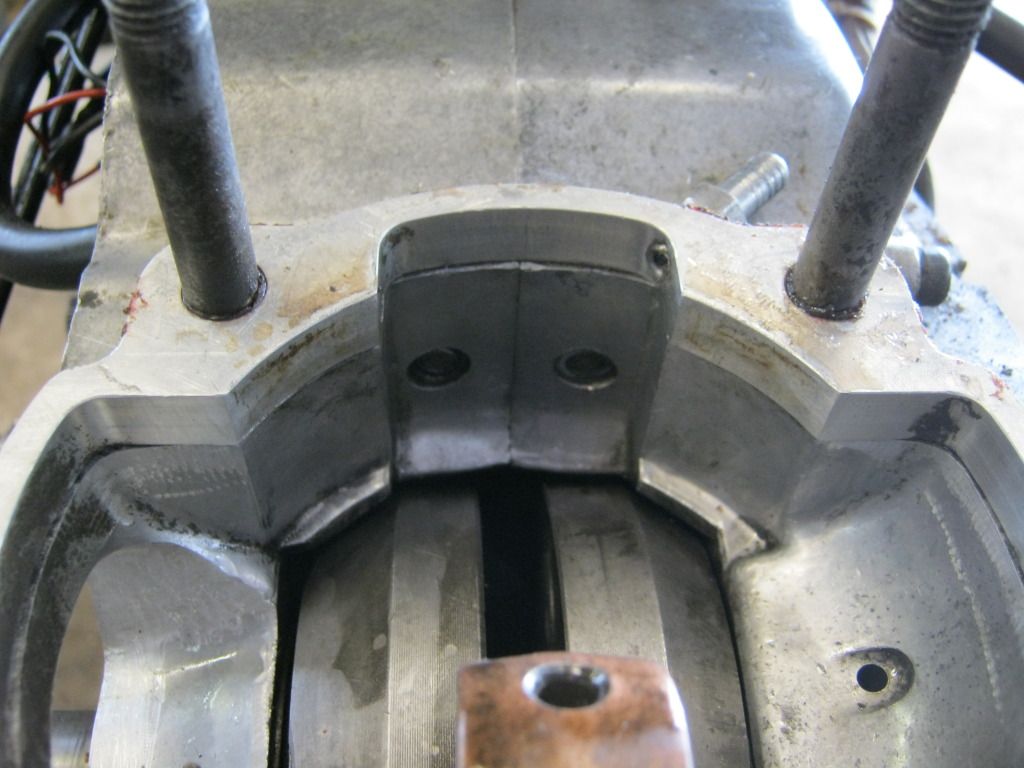
    Here is a pic of one I have just done, that happened to have a tapered spigot - enabling the Aux ducts to be run all the way down into the pipe.
    Check the big rad on the transfer duct/bore edge.
    Quote Originally Posted by wobbly View Post
    In all the engines I have done the area at the flange face is approx equal to the main port effective area, or approx .75 of all 3 ports.
    The header diameter is equal to the effective total of all three ports.
    Quote Originally Posted by Frits Overmars View Post
    ... you will have one less servo system. You know my view on construction in general and on racing equipment in particular: every part that you can leave out, doesn't cost anything, doesn't weigh anything, and never breaks down.
    Quote Originally Posted by Frits Overmars View Post
    The only difference is the end cone restrictor diameter: it's 23.3 mm for the 102 and 23.0 mm for the 106 (or the other way around; I can never remember which is which). One was for the 125 cc and the other was for the 250. As the 125 is on full song for a much greater part of the track than the 250, the restrictor difference should compensate for the EGT build-up. Personally I would never go below 23.3 mm with that kind of horsepower.
    Quote Originally Posted by teriks View Post
    Some have already seen this, but four those not involved in the project or reading twostrokemotocross.com:
    A Kiwi doing Ignitech controlled variable intake timing, plus fuel injection on a two-stroke.
    Link: http://twostrokemotocross.com/forum/...ke-article/15/
    Plenty of clever folks there on the opposite side of the globe...
    Quote Originally Posted by wobbly View Post
    I did a huge testing project a few years ago on Honda CR125 for SKUSA box stock racing in karts.
    22mm was as small as I could go sitting dead on 40 Hp at the gearbox,going lower made it finicky to tuning and made no more power - 22.5 made less power.
    Although the pipe is a tech item I was able to hide a "tailpipe nozzle " easily enough for testing and racing.
    But also from experience that is about the limit on power and tailpipe nozzle size in all sorts of applications.

  5. #9140
    Join Date
    2nd July 2011 - 08:25
    Bike
    2006, KTM, 250 SX
    Location
    Sweden
    Posts
    282
    Some have already seen this, but four those not involved in the project or reading twostrokemotocross.com:

    A Kiwi doing Ignitech controlled variable intake timing, plus fuel injection on a two-stroke.
    Link: http://twostrokemotocross.com/forum/...ke-article/15/
    Quote Originally Posted by Uniflow at TSM
    Why wait, do it yourselves, the technology is already out there. I use a Link Atom computer on my MX twostroke. Rear transfer port injection, by staging the injection, fuel wastage is reduced, more power, wider power spread. Enough oil deposit on the transfer runs down to the crankcase to service the bigend. It's been running for about eight months now. Yes there has been may issues.
    Quote Originally Posted by Uniflow at TSM
    The bike I have fuel injected is Kawasaki 350 Bighorn 1973. This only a test hack. A VMX bike.
    Quote Originally Posted by Uniflow at TSM
    Ignore the bike. The EFI that it run's on now is off the shelf components, Link EFI, car injectors, bosch fuel pump, Subaru relief valve. You can see the injector nozzles in the in the back of the crankcase ( x2).
    Quote Originally Posted by Uniflow at TSM
    This bike has a vairable rotary valve housing operated by the Ignitec ignition. From 55 degrees valve closing at low speed to 78 Degrees at full throttle.
    Quote Originally Posted by Uniflow at TSM
    Fueling changes. Link EFI has the ability to change the fueling as the head temp changes. With Ethanol the fuel requirement changes above 70 degrees C, more fuel required. This can be changed on a graph that uses TPS and Temp. This information is overlaid the main fuel map. Very handy with an air cooled engine.
    Quote Originally Posted by Uniflow at TSM
    The rod is a Hot Rod, to suit a Polarus trail boss. Five mm longer and I had to bore the crank flywheels out one mm. I offset the holes half a mm to get an extra one mm stroke. It is a much better rod than original. Piston is also Wiseco trail boss.
    An exhaust power valve would be next on the development list.
    I think this engine is as far as I want to go with development, I only did it to see if it could be done, EFI that is. I bought a YZF 250 to start the next development, throw the engine out and fit a 350 twostroke with EFI. This new water cooled engine will have a powervalve and I would like to use the vairable rotary valve again as it shows good results. Probably will run it on ethanol again as well. Trouble is, Meagan my daughter thinks the YZF is her's now and is using for trail riding. The new engine will probably take a little time to build up anyway.
    Quote Originally Posted by Uniflow at TSM
    The rotary valve still organizes the air into the crankcase, just has no fuel with it. Oil is still deposited from the injected fuel around the crank case and rotary valve via deposits in the transfer ports. One of the problems with the Link computer is some it's twostroke injection timing software is not operational yet. I can change the start of injection timing to a given point with the "on time" moving away from this point. I'm injecting approx over 180 degrees at full throttle (180 degrees injector on time ), so I have to set the start at approx 20 degrees after TDC ( quite a way before transfers open) so that at full throttle there is no injection still happening after transfer closes. If injection occurs after transfer port shut the fuel mixture on the next cycle is not so accurate ( power loss ). This I have found. Best it to have a fixed shut time ( approx 30 degrees before transfers shut ) and have the injection start vary. This will bring max injector start time to about 30 degrees ATDC at full throttle. This is what is needed, as up to about one third throttle is happening as the transfer is occurring. This I have found gives best bottom end power. Clear as mud?
    Quote Originally Posted by Uniflow at TSM
    In a nutshell, the injection timing is important. I can see why it's probably a good idea to use a small and a large injector, staged. The Link software is not able to do this in " twostroke mode" . Also there is an option to nail down the injector finish time and adjust the start time, or a center and adjust either way from that point. Also not available in twostroke mode. These options are available in fourstroke mode. So next step is to call the bike a fourstroke twin, 360 degree firing ( I don't need to use the ignition as this is done with a separate unit), This will use two drivers ( switches ) in the Link unit to run each cylinder ( if it were a twin ). Both drivers can be hooked together to run my pair of injectors each 360 degree cycle. This requires a cam sensor, I'll use a circuit called a flip flop connected to the ignition trigger ( single pulse per rev ). This circuit ( flip flop ) will only allow every second pulse to be seen by the Link computer, as far as the computer is concerned, a cam sensor. This will trick the computer in doing what I need it to do. Now all these options will be available. New Link soft wear will be available in eight months. I can't wait that long, I want it now.
    That's a big nutshell.
    Plenty of clever folks there on the opposite side of the globe...

  6. #9141
    Join Date
    8th February 2007 - 20:42
    Bike
    TZ400
    Location
    tAURANGA
    Posts
    4,088
    Have to reduce the Aprilia power output to down around 40 Hp to fit a 22.3 nozzle Frits.
    Ive got a thing thats unique and new.To prove it I'll have the last laugh on you.Cause instead of one head I got two.And you know two heads are better than one.

  7. #9142
    Join Date
    20th April 2011 - 08:45
    Bike
    none
    Location
    Raalte, Netherlands
    Posts
    3,396
    Quote Originally Posted by dinamik2t View Post
    I think the 102 has 23.3 restriction, based on the schematic in your files, Frits.
    Thanks, Dinamik. I corrected the typos in my previous post.

  8. #9143
    Join Date
    29th December 2011 - 04:14
    Bike
    rd 350 ypvs 1985
    Location
    netherlands
    Posts
    188
    Wob, are you saying you put that in engmod and got det warning when going higher then 40 hp when using 22.3 mm?

  9. #9144
    Join Date
    8th February 2007 - 20:42
    Bike
    TZ400
    Location
    tAURANGA
    Posts
    4,088
    I did a huge testing project a few years ago on Honda CR125 for SKUSA box stock racing in karts.
    22mm was as small as I could go sitting dead on 40 Hp at the gearbox,going lower made it finicky to tuning and made no more power - 22.5 made less power.
    Although the pipe is a tech item I was able to hide a "tailpipe nozzle " easily enough for testing and racing.

    But also from experience that is about the limit on power and tailpipe nozzle size in all sorts of applications.
    Ive got a thing thats unique and new.To prove it I'll have the last laugh on you.Cause instead of one head I got two.And you know two heads are better than one.

  10. #9145
    Join Date
    12th May 2011 - 23:52
    Bike
    razor scooter(pink)
    Location
    Australia
    Posts
    371
    Quote Originally Posted by dmcca View Post
    Sounds interesting, any pics or vid of it in action?
    It is at home at the moment(owner wants more.....) started it up once at home and it is truely loud and obnoxious beast, ask Jeram he was there. A normal chainsaw noise with a ear piercing shriek from the chamber on top

    Aprilia switched from NGK to Denso because parts of the isolator fell into the cylinder
    Joined the Denso revolution a few years ago when I had a few NGK new-out-of-the box failures.

  11. #9146
    Join Date
    18th May 2007 - 20:23
    Bike
    RG50 and 76 Suzuki GP125 Buckets
    Location
    Auckland
    Posts
    10,516
    Click image for larger version. 

Name:	H100 Ign 001.jpg 
Views:	88 
Size:	235.0 KB 
ID:	270406

    This week I have been working on a push and go, no battery required ignition for the Grandsons F5 Honda 100. The ignition was cobbled together from a Jaycar CDI kit and Suzuki trigger and coil. It took a couple of nights of playing around putting the kit together and getting a positive leading edge on the trigger wave form.

    A 230 to 9 Volt transformer was connected back to front with the 9V side connected to the Std 6V Honda generator coil and the 230V side charges the CDI capacitors. The points cam lobe was ground away around most of the cam leaving only a small part of the original lobe to excite the trigger.

    Got a nice blue spark tonight and its even timed right, so tidy the wiring up next week and the ignition should be ready to go.

  12. #9147
    Join Date
    11th July 2008 - 03:59
    Bike
    N/A
    Location
    Greece
    Posts
    388
    Wob, I have a question about EngMod results, if you have some time to spare.
    I remember your comment about 'silly long headers'. I have the following and a 61X54.5 engine, which in sim is around 47hp (even at 0.83Ceff), but dynoed only to 34.5hp.

    Click image for larger version. 

Name:	Pipe.YYPangSPR-N.gif 
Views:	244 
Size:	85.8 KB 
ID:	270498Click image for larger version. 

Name:	Untitled.gif 
Views:	189 
Size:	30.5 KB 
ID:	270499

    All the other parameters seem to be realistic, according to your guidance. I wonder whether this pipe could create a simulation over-prediction.
    The thing is, I know neither the AFR nor the ADV curve, but the person to tune it on the dyno is supposed to have experience with these engines.


    Furthermore, could you point out a few things, that a novice tuner should pay extra attention when assembling an engine, so that it's done correctly -like tolerances or similar things (??) ?

  13. #9148
    Join Date
    12th May 2011 - 23:52
    Bike
    razor scooter(pink)
    Location
    Australia
    Posts
    371
    The screen grab looks very good. That's very over square dimensions, 144mx'ers don't add much peak hp but add a fair bit of area under the curve.

  14. #9149
    Join Date
    11th July 2008 - 03:59
    Bike
    N/A
    Location
    Greece
    Posts
    388
    It is indeed too oversquare, but unfortunately that was a given with this engine, nothing I could do. So was the pipe design. We added auxiliary EX ports to help TA and according to EngMod, it was enough for about 52hp.
    I simulated the worst engine possible and still got 47, so I am definately missing something, either in inputs or assembly.

  15. #9150
    Join Date
    8th February 2007 - 20:42
    Bike
    TZ400
    Location
    tAURANGA
    Posts
    4,088
    The pipe does indeed have a silly header, but the angle is close to what the second stage of a 2 stage header would have.
    It then extends into what would normally be a shallow first diffuser cone.
    The result is that the main diffuser is pretty steep, so its this that is giving the good depression around BDC - and the reasonable power delivery at that rpm.
    The Aux ports are giving good blowdown , as there is only a small pressure rise when the transfers open.
    So many small details affect the real power delivery, and I would have to write a book with 30 chapters to even begin to point you in the right direction
    as far as correct assembly is concerned - and its this, that my customers are paying for.
    Ive got a thing thats unique and new.To prove it I'll have the last laugh on you.Cause instead of one head I got two.And you know two heads are better than one.

Thread Information

Users Browsing this Thread

There are currently 4 users browsing this thread. (1 members and 3 guests)

  1. Spetro

Posting Permissions

  • You may not post new threads
  • You may not post replies
  • You may not post attachments
  • You may not edit your posts
  •