That looks like a great job for a 3D printer.Originally Posted by husaberg


 Forum whore

That looks like a great job for a 3D printer.
Anorak

Are you speaking American Jason? It was done with tools and stuff.........

Kinky is using a feather. Perverted is using the whole chicken
Muddler/Dabbler.
FLETTNER
Guess you made the cranks for the little boxer yourself (except rods). What material do you use? case hardening steel or hi tensile?
Why a twin?
Forum whore
Yes I see that. What I ment was it COULD be done on a 3D printer.
No8 Wire Extraordinaire
Instead of a V4. Good point. Next F4 project?
Don't you look at my accountant.
He's the only one I've got.
Forum whore
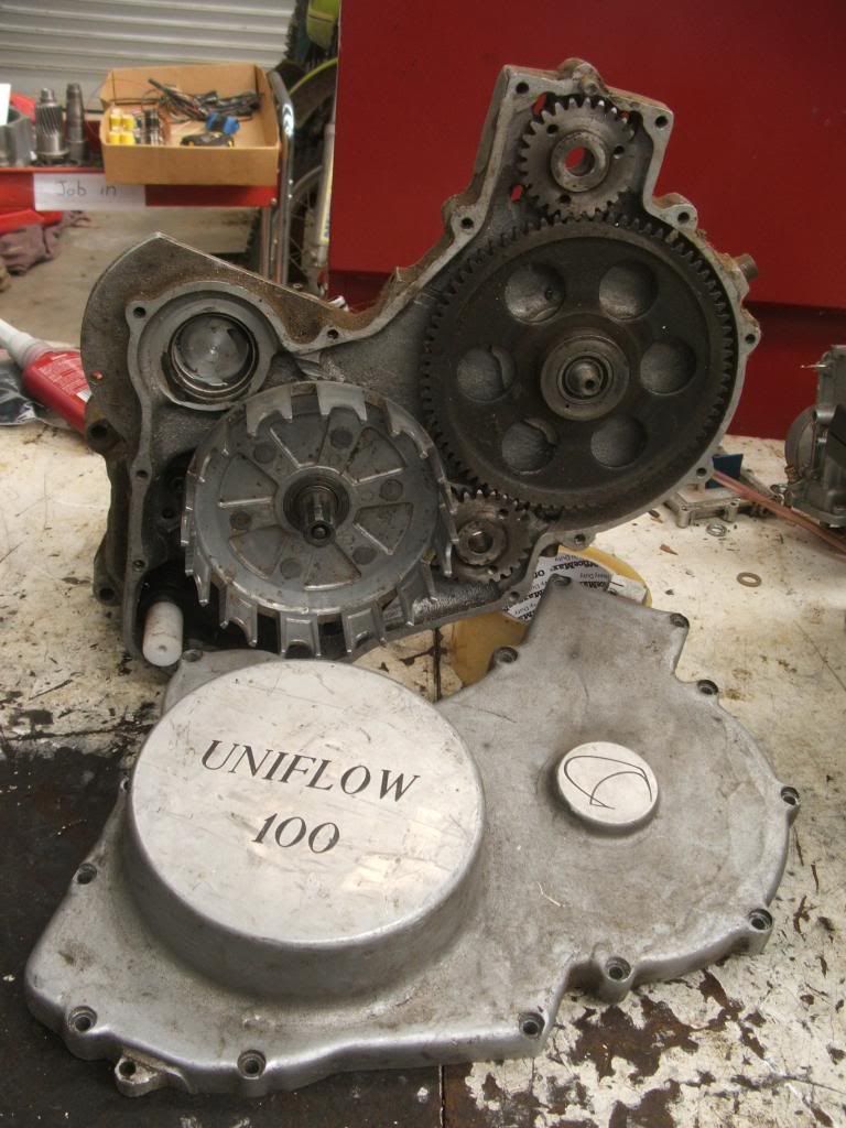
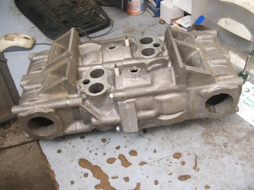
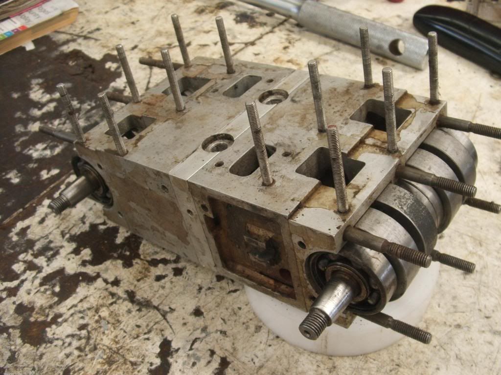
I made these crank parts years ago ( uniflow engine ), decided they would do better being used.
Crank halves are made of 4140, not hardended but I might nitride them this time. The center offset pin part is new and is made of EN39B to be case hardened, this part is away being stress relieved at the moment. The idea behind a horrizontal opp twin is for ballance ( so the bloody thing won't vibrate up in the rotorhead ). I thought if I made a reasonable job of the cylinder ( porting ) them the same cylinder design could be used for a 50cc twin or a 100cc four. Perhaps?
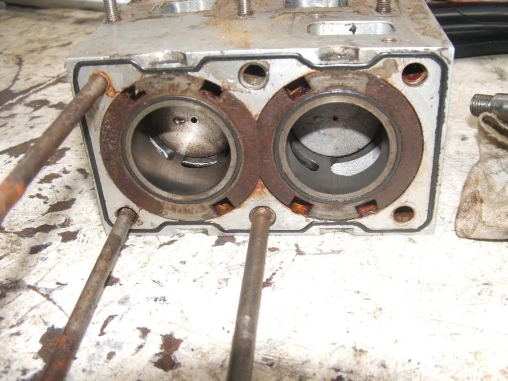
This is one of the uniflow cranks. There is a 6 degree lead on the exhaust piston, lots of blow down time.
I know I've posted these pictures before.
Muddler/Dabbler.
Geez mate, you have done all the sort of things that I used to dream about doing! I'm afraid I'm a "gunna". Just goes to show, you never should throw anything away, might come in handy, eh!
How did the uniflow 100 go anyway? guess it would be a little costly to manufacture?
I hadn't seen the pictures before as I still haven't waded through them all as yet.
Having said that, I fired up my furnace yesterday - not quite finished it yet but I couldn't resist doing a premature test firing! - got to make some tongs for the crucible now and try my first melt. I'm doing a "complete" plaster mould for speed and simplicity ( I need to learn the art of sand moulding before trying that), this has a plastic pattern ( a T bar handle off a plastic ball valve) which will be burnt out in the furnace - don't really know how it'll go, but I'm definitely going to do it.
I think I was a little close to the house as I heard the eaves cracking from the exhaust heat, got to get out a bit further I reckon! The heat off those things is quite scary!
Muddler/Dabbler.
The big idler gear in the uniflow drive train reminds me of the gear train driving the DOHC on the Guzzi V8!
Forum whore
It had it's moments, it was an interesting project. Biggest problem was the sleeves, first nitrided steel, then chromed steel, then finally cast iron. The iron ring against the iron bore resulted in short ring life, approx 20 min.
I tried to cool the steel sleeves direct with water so the sleeve ended up very thin and would distort.
I have posted this before too but here is version two ( 440cc ) running in a boat. Best run is toward the end of the video, 9200 rpm. Home cast pistons.
Here is a new version ( 640cc ) that is waiting for nikasil bores, it's going to cost a lot so that's why it's put aside for the moment.
Muddler/Dabbler.
looks like the piston phasing is "four up four down" - how good is the balance? pretty good I should imagine. How would two opposing pistons at TDC and two opposing at BDC work? - guess you've tried that too!
If you were using tuned pipes would it be possible to just to use just one pipe successfully? (ie 4 up 4 down)
In the case of this engine, do you think it would make any difference at all whether the crankshafts were rotating in the same direction or contra rotating?
Forum whore
The way this odd ball engine works, it needs to have all the crankcases pumping together. Yes one chamber would work. When this 100cc engine was in the bike frame it used two chambers. 2x two into one. On the first engine cranks rotated the same, second engine cranks counter rotated. No difference both smooth. The new 640cc engine cranks will counter rotate again, driving two two bladed props, intermeshing, counter rotating. No torque output from the engine to frame mounting. Also canceled out gyroscopic effects.
Muddler/Dabbler.
Very good and very interesting about the gyroscopic effects being cancelled out, also the lack of vibration.
Would be worried about the diameter of a two bladed prop being restricted though? - unless they have a gearbox for each crank to position the prop shafts further apart - naw, forget that - silly solution!(just rambling on my part!). Three bladed?
It does seem like it might make a very good aircraft engine when you consider some of the benefits you've mentioned and which you certainly wouldn't get with a conventional engine.
I can remember the old Commer TS3 two stroke diesel trucks with their 3 cylinder opposed piston engines ( a bit different crank arrangement to your one), bit noisy maybe, but ran smooth as - a very successful engine! - possibly not a fantastic commercial success though, due to the post war doldrums.
http://www.oldengine.org/members/die...terts3/ts3.htm
Sorry, I'm really getting away from bikes or foundries now!
Forum whore
[IMG], or synchropter, produced by Anton Flettner of Germany. According to Yves Le Bec, the Flettner Fl 282 was the world's first series production helicopter.[1][/IMG]
Like this synchropter but as a pusher prop instead. I'm trying to put up a link but can't, Google Anton Flettner helicopter.
Anorak
http://www.aviastar.org/helicopters_...er_kolibri.php
http://www.aviastar.org/helicopters_...ettner-265.php
http://www.pprune.org/rotorheads/245...opments-9.html
http://en.wikipedia.org/wiki/Flettner_Fl_265
I know nothing about helicopter other than they are fun to fly in......The pioneer work of Anton Flettner is often overshadowed by the more publicised activities of his contemporaries Focke and Sikorsky; yet Flettner's first fully practical helicopter, the Fl 265, was far superior to the Fw 61 and made a successful free flight several months before the VS-300 began tethered flights. Flettner's first rotorcraft, flown in 1932, had a 2-blade rotor 29.87m in diameter, with a 30hp Anzani engine mounted part of the way along each blade driving a propeller - a form of propulsion similar to that used by the Italian Vittorio Isacco on his so-called 'helicogyros' developed in the U.S.S.R. in the 1930s. The Flettner machine made a successful tethered take-off, but later overturned during a gale and was written off. His next significant design was the Fl 184 single-seat autogyro; powered by a 150hp Sh.14 radial engine, it flew in 1935 and was due to be evaluated by the German Navy when it, too, was unfortunately destroyed. The next design was the Fl 185, whose prototype (D-EFLT) flew in 1936 and had a 3-blade main rotor. The centrally-mounted Sh.14A engine drove, in addition to the rotor, two small anti-torque propellers on outriggers each side of the cabin and a large cooling fan in the nose.
By this time, however, Flettner had developed the idea of counter-rotating, intermeshing twin rotors. Many of his advisers thought that the airflow disturbed by the intermeshing blades would make this system less efficient than one using a single rotor; but Flettner believed that any problems thus encountered would be more than offset by the reduced drag resulting from having no external rotor-carrying structure. He proved his point by installing such a system in the Fl 265, whose prototype (D-EFLV) flew in May 1939. At this time encouragement for the development of small helicopters came mostly from the German Navy, on whose behalf six Fl 265's had been ordered in 1938 with a view to developing a machine suitable for shipboard reconnaissance and anti-submarine patrol. Service trials of the Fl 265 were more than satisfactory, and plans were made for series production; but by this time work was well advanced on a later model, the Fl 282, which could carry a men and was more versatile. The RLM therefore agreed to wait for the Fl 282, to hasten whose development it ordered thirty prototypes and fifteen pre-production aircraft in spring 1940. Maiden flight was made in 1941. The first three prototypes were completed as single-seaters and had fully enclosed cabins made up of a series of optically flat Plexiglas panels, faired-in rotor pylons and well-contoured fuselages. The Fl 282V3 was fitted with endplate auxiliary fins and a long underfin beneath the rear fuselage. Later machines had more utilitarian bodies and some had semi-enclosed cockpits; others, like the example illustrated, had a completely open pilot's seat.
Kinky is using a feather. Perverted is using the whole chicken
Muddler/Dabbler.
Are you likely to have a CV joint or something at the end of each crank in order to "splay" (for want of a better word) the axes of each prop shaft, in order to prevent the prop tips touching? as in the helicopter?
I have seen videos of that helicopter being pubicly displayed and flown in Berlin (I think) by Hanna Reitsch
.
Pity that war ever happened - it probably wiped out a lot of good brains on all sides!
All very interesting.
BTW, Have you seen the fast gyro/trike by the Dutch company (fast both on the road and in the air)? - extremely impressive! - again HUSA will no doubt do the honours!
http://pal-v.com/ (Video under Press/Media.)
There are currently 1 users browsing this thread. (0 members and 1 guests)
 Posting Permissions

 Reply With Quote
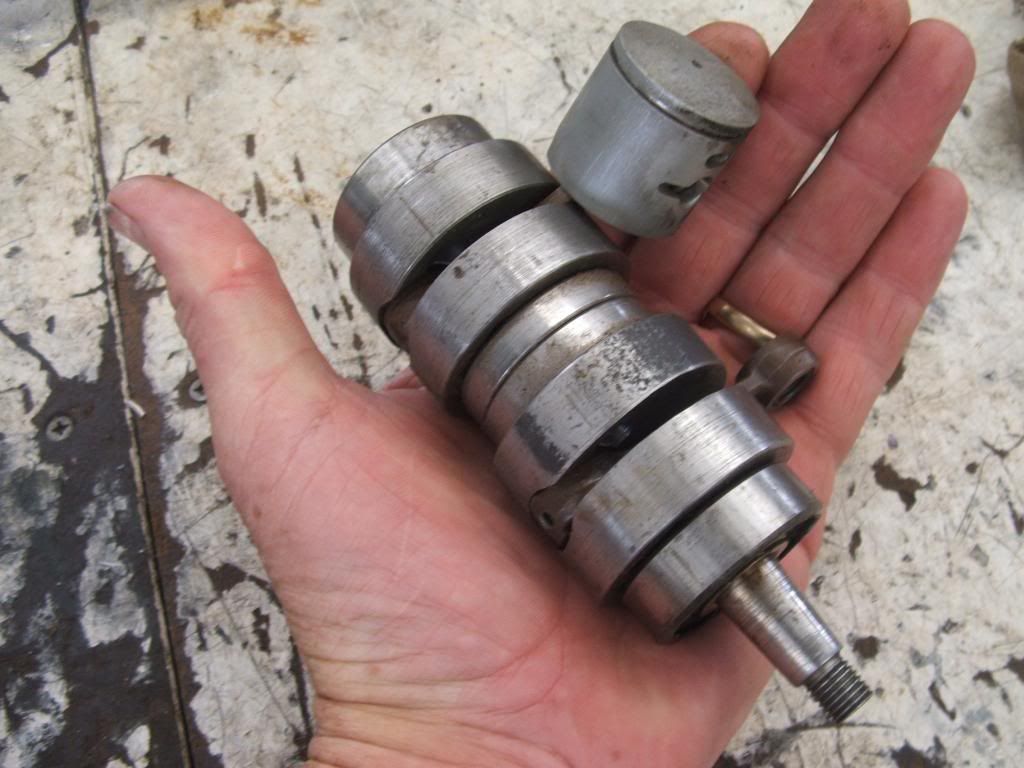
Bookmarks