Page 874 of 2629 FirstFirst ... 37477482486487287387487587688492497413741874 ... LastLast
Results 13,096 to 13,110 of 39427

Thread: ESE's works engine tuner

  1. #13096
    Join Date
    25th March 2009 - 23:55
    Bike
    Honda Cub
    Location
    Mars
    Posts
    49
    I'm going with sleeve valve as well..

  2. #13097
    Join Date
    12th February 2004 - 10:29
    Bike
    bucket FZR/MB100
    Location
    Henderson, Waitakere
    Posts
    4,200
    sleeve valve but as usual Neil has a twist, or not a twist as the case may be!!!

  3. #13098
    Join Date
    12th March 2010 - 16:56
    Bike
    TT500 F9 Kawasaki EFI
    Location
    Hamilton New Zealand
    Posts
    2,764
    SOO, no major aqruments against sleeve valve? Yes sleeve valve, as per the RR Crecy. I too would not belive a sleeve valve was a workable solution but if you read the reports on the Crecy development by Harry Riccardo there were some pretty impressive results. 1000 hours, 380 ish BMEP, 14 lbs boost on the V twin test engine. There was a lot of trouble with the sleeve for a start, until they were nitrided and honed type finish. Sleeve is open ended, does not rotate ( it did rotate a little in the Crecy because of the drive system ).
    So, why not?

  4. #13099
    Join Date
    18th May 2007 - 20:23
    Bike
    RG50 and 76 Suzuki GP125 Buckets
    Location
    Auckland
    Posts
    10,479


    Click image for larger version. 

Name:	RR Crecy.gif 
Views:	539 
Size:	243.3 KB 
ID:	290165

    Crecy Engine and 15,000rpm, I want one.

  5. #13100
    Join Date
    20th January 2010 - 14:41
    Bike
    husaberg
    Location
    The Wild Wild West
    Posts
    11,835
    Quote Originally Posted by TZ350 View Post

    Crecy Engine and 15,000rpm, I want one.
    Were they louder or quieter than a conventional engine?
    Quote Originally Posted by Katman View Post
    I reminder distinctly .


    Kinky is using a feather. Perverted is using the whole chicken

  6. #13101
    Join Date
    18th May 2007 - 20:23
    Bike
    RG50 and 76 Suzuki GP125 Buckets
    Location
    Auckland
    Posts
    10,479
    Quote Originally Posted by TZ350 View Post
    ...the timing of the Injection end point is critical on a two stroke and should be timed to end at transfer port closing ...

    Flettner suggested to me a way of making a trigger mechanism for a timing light that will show where the injection points are.

    Its basically a 12V solenoid coil with 14 Ohms DC resistance or there abouts. Fitted with a mild steel core and a CDI trigger coil attached so its pole piece is held firmly against the mild steel core of the solenoid coil. Then the solenoid coil is plugged into the injector socket. Connect the CDI trigger to something like an Ignitec set on zero advance and ignition coil and spark plug and by using a timing light and by reversing the solenoid coil connections back and forth you can see the injection end point and starting point.

    Clever idea I reckon.
    First cut at verifying the timing of the injection end point.

    Click image for larger version. 

Name:	EFI Timing 1 009.jpg 
Views:	55 
Size:	224.0 KB 
ID:	290171

    Fitted a pointer and drew a line at TDC and marked out the transfer duration.

    Click image for larger version. 

Name:	EFI Timing 1 001.jpg 
Views:	45 
Size:	239.7 KB 
ID:	290172Click image for larger version. 

Name:	EFI Timing 1 003.jpg 
Views:	38 
Size:	251.5 KB 
ID:	290173

    Lashed a regular trigger coil to a 12V solenoid with a bolt through it.

    Click image for larger version. 

Name:	EFI Timing 1 007.jpg 
Views:	41 
Size:	242.7 KB 
ID:	290175

    An analog volt meter is great for checking for pulsed signals.

    Any time there is a pulse the needle flicks, easy to see, you just can't do that with a digital meter, they don't react fast enough.

    Click image for larger version. 

Name:	EFI Timing 1 005.jpg 
Views:	34 
Size:	240.0 KB 
ID:	290174

    Connected the solenoid coil to the injector plug and the new trigger coil to the Ignitecs trigger input.

    Click image for larger version. 

Name:	EFI + Ignitec.JPG 
Views:	36 
Size:	115.4 KB 
ID:	290177

    Set the Ignitec map to zero, now it will fire immediately it sees a trigger pulse (well, actually it fires 360 degrees later, but it looks like its immediately and its in the same position the pulse occurred).

    Spun it up using the dyno as a starter motor I could get sparks using the regular trigger but I could not get anything from the lashed up solenoid/trigger coil arrangement.

    But from looking at the various Voltages I can see that the injector is pulsed by momentarily grounding one side, this applys 12V across it, (otherwise both sides are at the same potential, 12V). I couldn't see a corresponding pulse from the solenoid/trigger lashup, maybe to much inductance in the solenoid coil for it to react properly to the 2ms pulse. Might have to make something using a transistor Schmit trigger.

    Got the recipe wrong somewhere, no problems, plenty to think about and another day tomorrow.

  7. #13102
    Join Date
    13th June 2010 - 17:47
    Bike
    Exercycle
    Location
    Out in the cold
    Posts
    5,653
    Most inductive type pickups can be tested by flicking a screwdriver across them which suggests it's the collapse of the magnetic field which triggers the pulse. Either having your pickup attatched to the core gives too large a residual field and no triggering or maybe try a non magnetic bolt...
    Is there enough current in the 12v feed/trigger wire to the injectors to work a standard battery powered inductive timing light ?

  8. #13103
    Join Date
    2nd July 2013 - 11:52
    Bike
    GPR150
    Location
    palmertson north
    Posts
    2,389
    Quote Originally Posted by TZ350 View Post


    Click image for larger version. 

Name:	RR Crecy.gif 
Views:	539 
Size:	243.3 KB 
ID:	290165

    Crecy Engine and 15,000rpm, I want one.
    some where around i have the cut away pics of a flat twin 125cc sliding sleve race engine 38 odd hp , can't lay my hands on it )-: maybe husaberg could find it (-:

  9. #13104
    Join Date
    20th January 2010 - 14:41
    Bike
    husaberg
    Location
    The Wild Wild West
    Posts
    11,835
    Quote Originally Posted by mr bucketracer View Post
    some where around i have the cut away pics of a flat twin 125cc sliding sleve race engine 38 odd hp , can't lay my hands on it )-: maybe husaberg could find it (-:
    What am i a librarian
    http://www.kiwibiker.co.nz/forums/sh...post1130455718
    probably around here somewhere that's when we were talking about them.

    if you posted it it will be in your posts won't it you can search the stuff you linked as well?

    was it the ken duckworth one?
    Quote Originally Posted by husaberg View Post
    Bar and Stroud was a popular sleeve valve engine to be fitted to the early motor cycles. such as Grindley pearless a make later made famous by one C.W.G (Bill) Lacey. (He used J.A.P conventional engines Though)
    These engines were popular partly because of there almost silent operation.
    unfortuantly it was never developed to the same extent as the multi cylinders used on the aeroplanes and and for cars.
    This was also it the wiki article TZee quoted which i found interesting.

    http://en.wikipedia.org/wiki/Sleeve_valve


    Most of these advantages were evaluated and established during the 1920s by Sir Harry Ricardo, possibly the sleeve-valve engine's greatest advocate. He conceded that some of these advantages were significantly eroded as fuels improved up to and during World War II and as sodium-cooled exhaust valves were introduced in high output aircraft engines.


    Mike Hewland with his assistant John Logan, and Keith Duckworth experimented with a single-cylinder sleeve-valve test engine when looking at Cosworth DFV replacements. Hewland claimed to have obtained 72 hp (54 kW) from a 500 cc single-cylinder engine, with a specific fuel consumption of 170 gr/HP/hr -.45 to .39 lb/hp/hr-, the engine being able to work on creosote, with no specific lubrication supply for the sleeve, just the sleeve driving mechanism requires an specially devoted lubrication. Hewland reported also that the highest temperature measured in the cylinder head didn't exceed 150 °C, sleeve temperatures were around 140 °C, T was 270 °C in the center of cylinder and 240 °C in the edge.

    A recent SAE paper deals with a high-speed, small-displacement sleeve-valve engine, calculated, but not experimentally shown, to have a higher SFC than the poppet-valve alternative, a non-surprising result, considering the difficulty in obtaining the high intake and exhaust overlap that very fast-running engines require, additional work compares two different side-opening intake strategies for sleeve-valve engines.
    Quote Originally Posted by Katman View Post
    I reminder distinctly .


    Kinky is using a feather. Perverted is using the whole chicken

  10. #13105
    Join Date
    12th March 2010 - 16:56
    Bike
    TT500 F9 Kawasaki EFI
    Location
    Hamilton New Zealand
    Posts
    2,764
    It's a bit of a long shot but I just would like to have a go at testing a sleeve valve unit.
    The piston now will get an easier life with no exhaust to control and no exhaust wash across its edge. Piston can be short as it does not have to cover an exhaust port any more. System total friction will increase but piston to sleeve friction should decrease as they are both moving together ( at different rates ) also nitride is slippery. Material choice for the casting may play a part ( silicon content ) at first I will make it in CC601 just because thats what we use for our gearbox housings. I do have a little LM13 ( 9% silicon I think ) in ingot laying around somewhere, probably in my storage facility ( the old cowshed out the back of the neighbours farm ). Yes if it was such a good idea why has it not been done before ( in small crankcase twostrokes )? I might find the answer to that when we test it, sometimes interesting results pop up that no one predicted. And yes there will be lugs on the side ( transfers ) to fit injectors, perhaps not at the start but if all works well EFI will be the next step.
    The real reason I'm so interested is this engine will not need an expensive nickasil bore, nitriding the sleeve is cheap, bore will just need to be machined aluminium.

  11. #13106
    Join Date
    18th May 2007 - 20:23
    Bike
    RG50 and 76 Suzuki GP125 Buckets
    Location
    Auckland
    Posts
    10,479
    Quote Originally Posted by TZ350 View Post
    ... verifying the timing of the injection end point.

    From looking at the various Voltages I can see that the injector is pulsed by momentarily grounding one side, this applys 12V across it, (otherwise both sides are at the same potential, 12V).
    Ok I was right about that.


    Click image for larger version. 

Name:	Fuel Inj.jpg 
Views:	36 
Size:	13.0 KB 
ID:	290181


    Fuel Injector Circuit.

    Click image for larger version. 

Name:	Wiring diagram for injector circuit.jpg 
Views:	47 
Size:	10.9 KB 
ID:	290180

    I want to see when the injector is pulsed so it looks like the trick will be to take a signal from between the fuel injector and mossfet injector driver.

    And feed it to the Ignitecs ignition trigger input then I can use a timing light in the conventional way to see where its all happening.

  12. #13107
    Join Date
    2nd July 2013 - 11:52
    Bike
    GPR150
    Location
    palmertson north
    Posts
    2,389

    Red face

    no mr husaberg , i have it in a book somwhere but seen you are the master of finding stuff on the net you could kind of go looking lol

  13. #13108
    Join Date
    12th March 2010 - 16:56
    Bike
    TT500 F9 Kawasaki EFI
    Location
    Hamilton New Zealand
    Posts
    2,764
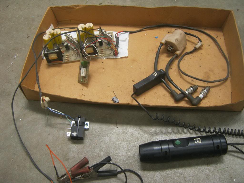
    Many years ago when the uniflow appeared at the Ohakea GP, racing was halted because someones ignition was upsetting the tower transmitting. New Zealand was held defenceless for an hour while we all had to ride past the tower one by one to see who was the calprit. What you see here was the problem, my home made CDI. You would not want to touch it when it's running, it will jump 4"
    This is what I've been using, set up as you see it, to strobe the injection timing on the Kawasaki. The little coil you can see has terminals that pluged in series to the injector coils. One polarity would see the magnetic field as the coils energised and the other polarity would see the field decay as the injectors are tuned off, magnetic coupling. Rough and ready but it works well when you don't have an oscilloscope.


  14. #13109
    Join Date
    25th March 2004 - 17:22
    Bike
    RZ496/Street 765RS/GasGas/ etc etc
    Location
    Wellington. . ok the hutt
    Posts
    20,563
    Blog Entries
    2
    Ahh, that was you?
    Don't you look at my accountant.
    He's the only one I've got.

  15. #13110
    Join Date
    5th April 2004 - 20:04
    Bike
    Exxon Valdez
    Location
    wellington
    Posts
    13,371
    Quote Originally Posted by TZ350 View Post
    Ok I was right about that.

    I want to see when the injector is pulsed so it looks like the trick will be to take a signal from between the fuel injector and mossfet injector driver.

    And feed it to the Ignitecs ignition trigger input then I can use a timing light in the conventional way to see where its all happening.
    Didn't this get dicussed in the ignitec thread?

    I thought everything switched injectors and coils through earth? I haven't looked into it, but I figured that since a charge takes time to build, it's the economical way to do it.

    Might just be me seeing things wrong like normal though.

Thread Information

Users Browsing this Thread

There are currently 129 users browsing this thread. (0 members and 129 guests)

Posting Permissions

  • You may not post new threads
  • You may not post replies
  • You may not post attachments
  • You may not edit your posts
  •