The mass asymmetry in those Aprilia cranks is there purely for balancing reasons; it has nothing to do with 'rotating up' or 'rotating down'.Originally Posted by senso

For all I know rotating means going round, not up or down.

 Forum whore

The mass asymmetry in those Aprilia cranks is there purely for balancing reasons; it has nothing to do with 'rotating up' or 'rotating down'.
For all I know rotating means going round, not up or down
Forum whore
So looking at a single crank - end on that spins clockwise, you would bias the balance mass ( if using Mallory opposite the crank )
slightly clockwise of the vertical centreline thru the pin.
Or if using holes each side of the pin, there would be a smaller hole to the right, and a bigger hole to the left of the pin ( irrelevant if they are alloy filled or not for this discussion ).
And the purpose of the bias is to advance the cranks rotational inertia such that this aids acceleration away from BDC and TDC - right?
But what advantage would this give - I will have to go read Dr Dixon to see if he mentions some perceived benefit.
Ive got a thing thats unique and new.To prove it I'll have the last laugh on you.Cause instead of one head I got two.And you know two heads are better than one.
Fair weather rider

My up and down are regarding going to TDC or to BDC, the piston goes "up" and "down".
I don't have the book here, but its just a short paragraph, its basically explaining the term, and nothing more if I remember correctly.
Forum whore

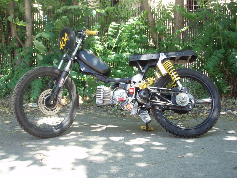
I love these original moped race builds and the ideas that go into them, very Bucketerish.
http://garage.1977mopeds.com/build/B...Old+iezer+v3.0
Sometimes more art than function:- https://youtu.be/LYfzI5nLC2w
And
http://garage.1977mopeds.com/build/Mono+Maxi
Other interesting builds here:- http://garage.1977mopeds.com/browse/.../?product=3220
No8 Wire Extraordinaire
Those tyres look like they could kill, as could the front brake line.
Don't you look at my accountant.
He's the only one I've got.
Hardcore Biker

One explanation from long ago was that a single was going to be a shaker in any case, and that the factory might choose to move the direction of the shaking to where it was easier on motor-mounts or the frame or the rider's hands or whatever.
Hardcore Biker
How about this for range - four variable pulleys.
http://garage.1977mopeds.com/build/Black+Betty+aka+VX4
Fair weather rider
Re crank weight offsets
Frits if I recall correctly. upon the pit lane thread you described the differing rotational speeds as a crankshaft moves through 360 degrees along with the crankshaft pulling the piston away from TDC in the overrev. Would this offset balance benefit in assisting the crank to rotate at a more even speed throughout a & each subsequent revolution along with stabilising the spark signal from the ignition rotor upon the crankshafts end ?
I hope I've recalled this correctly.
Moped rider

The only thing i can think of re: asymmetric balance mass is to slow the instant crank velocity close to BDC to give more transfer "Time" without an increase in degree opening. If the single cylinder is near vertical then the bigger weighted hole would have to be to the right of the pin so its interaction with gravity 'could' be allowed to slow the crank.
Maybe.
Forum whore
That is clever, I like it.
Hardcore Biker
My take is that, irrespective of where the counterbalance weights/holes are and even if they are asymmetric, will make no difference at all to the overall flywheel effect of the crank. All the crank is a lump of metal, which apart from its other functions, is a flywheel with a 2nd moment of mass around the crank axis.
However, it is possible that any asymmetry could provide an out of balance force vector that could oppose some (higher) connecting rod force acting on the crankpin, thereby minimising the force on the main bearings at a certain time over the cycle, maybe reducing friction. Could be crap though.
"Success is the ability to go from one failure to another with no loss of enthusiasm.
Bucket Racer/Crasher
Do people REALLY think that having the holes asymmetric is going to change the rate of change of crankshaft rotational velocity depending on crankshaft position, REALLY? The crank rotational inertia will remain constant irrespective of where the holes are, as long as the holes are the same size and the same distance from the centre of rotation, i.e. - the centre of the mainshafts. Their position about the circumference of the crank is not going to have an effect on the inertia and therefore the crankshaft speed changes that occur within a single revolution. Gravity will have an effect but good luck measuring that. The motorcycles rate of acceleration would have a similar effect but at 90degrees.
There might be a case for the asymmetry based on changes in crankshaft speed within a single revolution but I don't know how much a crankshaft changes speed from the compression to the power stroke. Obviously a bit or there would be no need for cush drives
Forum whore
Ken and Speedpro, I'd say you both nailed it.
The rotational speed variation is quite small, as is the angular position variation. The actual crankshaft position will never vary more than 0,5° compared to a truly uniform rpm, so its influence on port and ignition timings is just about negligible.
The cush drive is not there to smooth the rpm fluctuation but the torque fluctuation. The torque fluctuation can be ten times the nominal torque and if you don't do something about it, you will be forced to construct the whole transmission much heavier than necessary.

Fair weather rider
Here is one extreme example of asymmetric holes, its a crank for a sachs engine, with 48mm stroke(the original engine has 44mm stroke).

Forum whore
I once spent quite a bit of time as a Technician working on a prototype vertical cyclotron at ANAC (1980's) and gravity did have a measurable effect on the particles being spun around. Gravity would detract energy on the up side and added energy (speed) on the down side. Talking with the Physicist in charge, the challenge was timing the pushes and pulls of the accelerating plates to coincide with the particles passing, it wasn't symmetrical.
There are currently 20 users browsing this thread. (0 members and 20 guests)
 Posting Permissions

 Reply With Quote
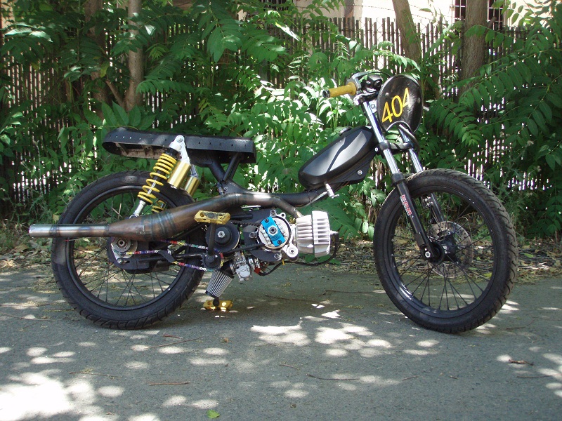
Bookmarks