Page 1500 of 2628 FirstFirst ... 50010001400145014901498149915001501150215101550160020002500 ... LastLast
Results 22,486 to 22,500 of 39408

Thread: ESE's works engine tuner

  1. #22486
    Join Date
    18th May 2007 - 20:23
    Bike
    RG50 and 76 Suzuki GP125 Buckets
    Location
    Auckland
    Posts
    10,479
    .

    Page ..... 1500 .... How to search within the ESE mega-thread?

    Quote Originally Posted by husaberg View Post
    Quote Originally Posted by seattle smitty View Post
    (Insert long sigh here) I hate, I hate to ask this, because I know I've seen the answer somewhere, the answer to various members' questions about how to narrow down a KB search. But as always, I'm unable to find this info (using Advance Search with every word combination I can think of). Generally my subject searches will refer me to the ESE thread. All ten thousand pages.
    When you use advanced search make sure you are searching with single content option tab at the top. It also helps to add in the user name. If you know who posted it.
    Quote Originally Posted by emess View Post
    Rather than use the site search which usually fails, use Google so to search this site use an ordinary search phrase and after it add
    site:www.kiwibiker.co.nz
    for example
    Frits pisa site:www.kiwibiker.co.nz
    the same will work for other sites with the appropriate site address
    Mick
    Quote Originally Posted by Mike.Gayner View Post
    There's an even better way if you're wanting to search within a particular thread.

    For example if you wanted to search for “disc valve” in just the ESE thread, first you need to find the thread URL ID. Go into the ESE thread and grab the following info from the URL bar:

    kiwibiker.co.nz/forums/showthread.php/86554

    Now in google, search for: disc valve inurl:kiwibiker.co.nz/forums/showthread.php/86554

    Using inurl: will only return results that have the appended string in the URL, so this search will target only that thread.

    You might get just one result followed by text saying irrelevant results were omitted – just click “search with the omitted results included” to get a complete search.

    You’re going to want to make your search as specific as possible, and let Google do the ranking.

    edit: And just a quick follow up - don't even bother with the site's search. vBulletin search is notoriously useless, let Google do the leg work.
    Quote Originally Posted by TZ350 View Post
    Also page 500, 1000 and 1250 have a basic directory and a lot off the decade (10th) pages have their own small collections of quotes of interesting technical posts from the last few pages.
    There are over 7000 images on this thread, use "Thread Tools" to view them and then click through to the original post about them.

    Quote Originally Posted by TZ350 View Post
    How to view all the images.

    Attachment 293109

    Go to Thread Tools at the top of the page and View Thread Images.

    Attachment 293112

    Now roll to the bottom of the page.

    Attachment 293110

    Here you can sort them from the beginning.

    Attachment 293111

    70 to a page, there are 6,000+ images

    Attachment 293113

    If you find something interesting just click on the images title and it will take you to the original post.
    Quote Originally Posted by husaberg View Post
    http://www.kiwibiker.co.nz/forums/sh...post1130221509
    http://www.kiwibiker.co.nz/forums/sh...post1130224186

    Well over 200 people viewed the pics which by KB standards is a lot, as they had no cleavage.
    (I am not sure if this will work) but I have posted over 10,167 pics in KB

    http://www.kiwibiker.co.nz/forums/imgbrowser.php? Sorry you need to click on Husaberg view images set to begining set the image finder to 70 per page and by number of views.
    If you are looking for 2T tuning technical information. Because this is a show and tell thread, this thread is best read backwards, ie start at the last page and read back towards the beginning that way you get to read the answer without having to wade through the confused questions.

    A lot of the decade pages have collections of quotes and links to interesting things.

    Page 1500 Links List.
    Page 1490 Wiseco vis other pistons discussion.
    Page 1480 Discussion with data maps about why Marshengs bike runs hotter in the corners.
    Page 1470 Wiseco vis other pistons and their short comings.
    Page 1460 Page talks about HCCI. Bike catches fire at Wanganui Cemetery RR.
    Page 1450 Working with pumper carbs.
    Page 1440 The insides of the Ryger is revealed on this page.
    Page 1430 Pumper carb tuning talk.
    Page 1420 The Frepan TZ400 built by Wobbly. Lots of links and pictures.
    Page 1410 Air/Fuel ratio meter and how to use a Lambda sensor with a two stroke.
    Page 1400 2:1 Pipes, and the power advantages of cutting the Ex side of the piston short.
    Page 1390 EngMod2T, simulating and testing pipe designs.
    Page 1380 Dyno results, testing different sized air correction jets.
    Page 1370 Links to Rod/Piston kits and parts suppliers.
    Page 1360 Dyno results for some F5 Bucket 50cc bikes.
    Page 1350 To much talk about the Ryger so celebrating the work other people are doing in their sheds.
    Page 1340 Frits on why the ring peg should be at the 6 o’clock position.
    Page 1330 Peoples interesting projects.
    Page 1320 Links to Rods and Pistons technical data.
    Page 1310 Celebrating Kels very neat and rather quick KR125/RS project.
    Page 1300 Celebrating peoples home built racing projects.
    Page 1290 People doing real Bucket building stuff. Ryger uses up a lot of space from here on.
    Page 1280 Links to Peewee’s, Lightbulbs, Adegnes’s and Ken Seebers racing projects.
    Page 1270 Transfer Port Theory.
    Page 1260 Ex and Transfer port design with pictures.
    Page 1250 Links List
    Page 1240 2T development Software, Port Theory, Interesting Sites
    Page 1230 Compression Ratio, Ex duct shape and length, Fancy spark plugs.
    Page 1220 Reed Valve Petals, Oxygen Sensors, Exhaust duct step at the pipe flange.
    Page 1210 Ignition Trigger Woes, EngMod 2T and Blow-Down, Fuelling Curve.
    Page 1200 Frits on power spread and the ratio of the maximum and minimum points in the power band.
    Page 1190 No data, but a lot of talk about what the Ryger engine might look like.
    Page 1180 Frits on 2T fuel consumption. M50 cylinder portmap and EngMod2T analysis.
    Page 1170 Engine/Gearbox oils and bearings. Transfer duct shape and optimal Ex port timing.
    Page 1160 Frits - Engines need large crankcase volumes, Power vis Handling.
    Page 1150 Serious talk about crankcase volume.
    Page 1140 Measuring the transfer duct length, Ignitec, Expansion chamber design, Trombone pipe.
    Page 1130 Team GPR Edgecumbe Videos …. Cooling 2T’s …. 3xEx vis T port,
    Page 1120 Crank Balancing, Ceramic Coating, Plugs, Piston Edge chamfers, RS125 pipe dimensions.
    Page 1110 TeeZees progress on the EFI thing with the Beast.
    Page 1100 No Data but some talk about pickups and EngMod 2T transducer position in the pipe.
    Page 1090 Links about the Detonation Sensor and Temperature Data Logger.
    Page 1080 No Data, the plenum is protested, Frits on Blowdown and Transfer window height.
    Page 1070 Exhaust Duct shape, Kawasaki and BRC EFI dyno videos.
    Page 1060 No Data but talk about Port shape and Flow in a duct on this page.
    Page 1050 EngMod2T setup talk about pipes, transfer ports and the TubMax graph.
    Page 1040 Basics of pipe design and how to influence where the point of maximum depression occurs.
    Page 1030 Racing at Greymouth, its well worth a look to see Team GPR in action.
    Page 1020 Pipe dimensions, Seattle Smittys hydroplanes. Husaburgs piston link.
    Page 1010 Suspension Tuning.


    Page 1000 has a lot of useful information and links. http://www.kiwibiker.co.nz/forums/sh...post1130773139


    Quote Originally Posted by TZ350 View Post
    Page 990 Blowdown STA, Ex porting plated cylinders, port layout and port angles.
    Page 980 No links list but there is talk about spark energy and EGT
    Page 970 Fuel - Oil and EGT talk
    Page 960 Wob - Fuel and Oil Talk and Crank inertia.
    Page 950 Its all about exhaust blow down …..
    Page 940 Fixers 50cc adventures – ports & heads – Wob talks about Bad Gas.
    Page 930 Frits 50cc pipe – Husburgs large links list, parts books, steering head brgs
    Page 920 Big links list, allsorts. Tokoroa GP videos.
    Page 910 No links list but the page is about fitting a 12V generator stator.
    Page 900 Frits thoughts on O2 sensors – EFI Fueling theory – Wob on EGT
    Page 890 DIY Foundry tips – EFI data – Detonation Management (tec paper) – more EFI
    Page 880 Big list of Flettners Foundry posts and pictures.
    Page 870 YZ & Bighorn Dyno results – Dyno Vids and EFI talk
    Page 860 Air cooling and ducting and Carb air inlets, next page Greymouth Race
    Page 850 1st run of the EFI Beast
    Page 840 Husaburgs big links list on Power Jets – High temp epoxy and Ex port dam.
    Page 830 Plugging piston pins – Cyl Heads (no radius) and Plug to Piston distance.
    Page 820 Det sensor & Ignitec setup – Exhaust port dam – Boost Bottle – Insulating Paint
    Page 810 Links – about Razing the Exhaust port floor
    Page 800 Link to dyno graphs for the YZ & BigHorn EFI Bikes & a lot of EFI stuff
    Page 790 Car & bike museum pics _ Wobs pipe.
    Page 780 Setting up an IgniTec DC-CDI-Race-2 ignition – Big list of links.
    Page 770 Wobs views on triple ex ports – first run of the EFI YZ250
    Page 760 Port Angles – lots of Pipe design info – Fast model aero engine.
    Page 750 Case Com – Basic 2T tuning – BigHorn EFI
    Page 740 Case Vol – Deto – Inlet Length – Over rev deto.
    Page 730 Pipes – Deto – Lambda – Temp probes – CrankCase CR – Variable headers.
    Page 720 Inlet tract length – GP125 service manual – Picture of how to read a plug + Wobs comments
    Page 710 Fuel and Power Jets - EGT and CHT - Crank build
    Page 700 Talk about wide and low transfers – Case volume and dyno graph – det and Lambda sensors.
    Page 690 Pipe talk and ideas about making mufflers.
    Page 680 Talk about the Trombone pipe and more of Frits and Wobs views on pipes.
    Page 670 Pipes – blowdown STA numbers – Trombone pipe.
    Page 660 Lots of links on pipes – Ariel Arrow – and CVT
    Page 650 Links – Frits and Wobs views on pipes – CVT transmissions – 30 vis 24 carb dyno graph
    Page 640 Links to Wobs views on pipes – crank balance factor – connecting a laptop to the Ignitec
    Page 630 More of Wobs views on pipes – Frame & wheel weights – correct O ring grove sizes
    Page 620 Links to Cooling Water Flow – Case Comp and Pipes – Setting up 2T carburation.
    Page 610 Simulation packages – combustion efficiency – transfer ducts – chamfered exhaust top edge.
    Page 600 Books that can be down loaded and Frits talks about why 190 Ex duration is so good.
    Page 580 No links but page is about mounting carbs and the 24mm pumper carb & 28hp dyno graph.
    Page 570 No links but the page talks about carburation – emulsion tubes and pilot jets.
    Page 560 No links, the page is mostly about 96 vis Av gas with dyno test.
    Page 550 No links list but the page is mostly about TZ400 build and cranks and rods.
    Page 540 No links, the page is mostly about Wobs success with the 400 project.
    Page 530 Ignition – setting up det sensors without a dyno – wings inside reed valves – poly quad head
    Page 520 Mostly about what some wheels weigh, ATAC valves and crank stuffers.
    Page 510 Bucketracers general Links List
    Page 500 Bucketracers links list of how to make a mid 20’s hp Suzuki GP125

    Quote Originally Posted by bucketracer View Post
    Page 490 The Trombone, Ex port resonance and Transfer port stagger.
    Page 480 A vid of the Trombone, transfer timing and hot gases entering the transfers because of insufficient blow-down for the rpm.
    Page 470 Blow-down STA ... Specific Time Area.
    Page 460 No list but the page talks about Boost Bottles.
    Page 450 Links to the basic info for building a 30+ hp Bucket.
    Page 440 No list, page talks about power and air correction jets.
    Page 430 Carb inlet lengths and crankcase volumes.
    Page 420 Transfer ports and the importance of the up swept angles, the Leaning Tower of Pisa principle explained.
    Page 410 Rolling road dynos, main and power jet ratio.
    Page 400 Links to the basic info for building a 30hp Suzuki GP125 Bucket engine.
    Page 390 Links to Frits collection of Aprilia stuff.
    Page 380 Transfer duct shape and STA's.
    Page 370 No list but the page talks about Jan Thiel and racing 50's.
    Page 360 Frits chamber calculations formula.
    Page 350 PJ switching, Wob and crank shaft balance.
    Page 340 Muriatic Acid, main brg float, Husburgs con rod dimensions.
    Page 330 No list, page talks about expansion chambers, race gas.
    Page 320 High temp silicon, Yama Bond, crankcase sealing, air solenoids Vid clips of Mamola.
    Page 310 Copper for cooling, sprockets for cooling, steering head brgs.
    Page 300 How to determine STA numbers.
    Page 290 B/E dimensions, delivery ratio, Honda Ex Step, stinger nozzel
    Page 280 Aprilia RSA port layout explained, pumper carb, links to gluing up the GP cases.
    Page 270 Link list on how to make a decent high 20's hp Suzuki GP125 Bucket engine.
    Page 260 Over rev cough and what it means, Mallory metal for crank balancing.
    Page 250 27hp from a 1978 Suzuki GP125
    Page 240 Aprilia RSA cylinder stuff.
    Page 230 Porting Calculator and a lot of other useful tech links.
    Page 220 RG50 part numbers, 2-stroke carb atomisers explained
    Page 210 Page is mostly about the results from the TRRS
    Page 200 Simple 18 hp Suzuki GP Bucket engine using a RG250 pipe.


    Etc ...

    On Page 500, Bucket has links to how Team ESE built their Suzuki GP125 26, 28 and 31 hp engines:- http://www.kiwibiker.co.nz/forums/sh...-tuner/page500

    Quote Originally Posted by husaberg View Post
    Transfer Port theory
    Quote Originally Posted by mr bucketracer View Post
    Starting from the beginning I have been trying to find the posts that talk about pipes and collate and edit them. There is heaps of it, mostly from Wobbly and pages 620 630 640 650 660 670 680 690 700 710 720 730 740 750 760 770 780 1040 and 1050 have un edited collections of raw material.

  2. #22487
    Join Date
    18th May 2007 - 20:23
    Bike
    RG50 and 76 Suzuki GP125 Buckets
    Location
    Auckland
    Posts
    10,479
    Page 2 .... 1500

    New Zealand F4 Bucket racing.

    Quote Originally Posted by mr bucketracer View Post
    I want to see race 2 of this ....

    https://www.youtube.com/watch?v=HcK1As59jkI
    The great sound of a two stroke Bucket, real music.

    Quote Originally Posted by seymour14 View Post
    2016 Tokoroa GP

    Quote Originally Posted by Frits Overmars View Post
    Here are some pictures to help you on your way Peewee.
    Attachment 313049 Attachment 313050 Attachment 313051 Attachment 313052Attachment 313053
    Quote Originally Posted by wobbly View Post
    having a header say 28% or 36% of the tuned length will invariably produce huge holes in the torque curve - due to the incorrect positioning of the diffuser.

    Quote Originally Posted by wobbly View Post
    Cutting or sleeving headers to do a dyno test, is that simply doing that and trying to analyze the results is completely pointless if you have not measured the pipes beforehand to see what the original design intent was.


    If the header is short to start with, and you then shorten it more, the tuned length may be perfect, but the negative effect from the now silly short header length will overpower any of the good effects of the overall length.


    Conversely if the header was short and you lengthened it, the power increase may be mainly due to now having a " correct " % of header - though the pipe length may be completely wrong for the port timing.

    Quote Originally Posted by wobbly View Post
    The squish following the piston shape by using CNC is even more important if you are pushing the limits with around 50% SAR and very tight clearance. This also works together with the sharp edge into the bowl.

    Quote Originally Posted by Frits Overmars View Post
    As we were on the subject of scavenging angles, now would be a good time to write something about the radial angles of the A-transfers.


    Surely a duct with a radial angle of over 20° offers a smaller cross-section to the flow than a duct that enters the cylinder perpendicularly?


    Yes it does. But there are two good reasons to angle it upward anyway.


    First, perpendicular mixture streams coming from the A-ports would collide and slow one another right down. The upward angles provide for less velocity losses and less pressure losses, so despite their smaller cross-section, upward ports may flow as much, if not more, than perpendicular ports.


    (Now you may well ask why the B-ports do not get the same treatment; that is because the central scavenging column, resulting from all incoming scavenging streams together, must not have too much radial velocity, or the loop scavenging will result in a loop-loss into the exhaust).


    Second, there is a thing called scavenging balance (I invented the word for my personal use, so this may well be the first time you ever saw it).


    If you looked closely at the scavenging picture of the MB-cylinder I posted earlier today, you may have noticed that the 'radial scavenging directional resultant'
    had a value of 101,045°. 90° would have meant 'straight up'; more than 90° indicates that the central scavenging column is leaning towards the exhaust side of the cylinder.


    But we don't want that; it is bad for the scavenging of the rear part of the cylinder, and it is risky because it may provoke scavenging losses straight into the exhaust.


    But how can we prevent a scavenging column from toppling over to the exhaust side like the leaning tower of Pisa? Not by pushing against its basis, but by pushing higher up. Hence the radial angle of the A-ports.


    The pictures will tell the story. (If only the Pisa architect had known a bit more about two-stroke tuning....)

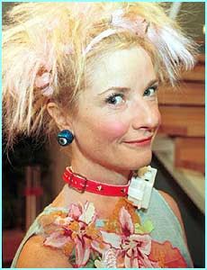
    The picture of the girl, its important transfer theory. You will have to go to page 1000 to read about it.
    Attached Thumbnails Attached Thumbnails Click image for larger version. 

Name:	Transfer Port Theory.jpg 
Views:	48 
Size:	21.6 KB 
ID:	320792   Click image for larger version. 

Name:	Frits Venturie.gif 
Views:	71 
Size:	6.1 KB 
ID:	320799   Click image for larger version. 

Name:	Frits Factors -2.JPG 
Views:	81 
Size:	73.1 KB 
ID:	320794   Click image for larger version. 

Name:	Tripple Port 75%.jpg 
Views:	90 
Size:	16.3 KB 
ID:	320798   Click image for larger version. 

Name:	Frits radial exhaust flow.jpg 
Views:	64 
Size:	36.8 KB 
ID:	320796   Click image for larger version. 

Name:	Plug Readings.jpeg 
Views:	77 
Size:	43.0 KB 
ID:	320797  

  3. #22488
    Join Date
    18th May 2007 - 20:23
    Bike
    RG50 and 76 Suzuki GP125 Buckets
    Location
    Auckland
    Posts
    10,479
    Page 3 .... 1500

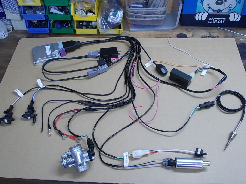
    The EFI story with pictures if you follow the links back to the original posts.

    Quote Originally Posted by TZ350 View Post
    Posted because someone asked where to find it all, so a recap on the basics of the Beasts Engine.
    Quote Originally Posted by bucketracer View Post
    TeeZee tested his 24 against a 30 in a back to back test. The 30 didn't make anymore power than the 24.
    Quote Originally Posted by TZ350 View Post
    Ok, making a bit of progress with setting up the EFI systems throttle body.
    Quote Originally Posted by TZ350 View Post
    Det Sensor. Next week I hope to get all the chopping and changing of the wiring done then I can start playing with setting up the Ecotrons EFI program for a trial run...
    Quote Originally Posted by TZ350 View Post
    The mid chamber bleed re visited as it might be useful for some low end boost......
    Quote Originally Posted by TZ350 View Post
    One of the most useful things I have added to the fuel injection system is a switch that turns the fuel pump off.
    Quote Originally Posted by TZ350 View Post
    Tim gave me a hand tonight, we started to make progress when we moved the injection end point. I think we originally had the injector squirting into closed ports.
    Quote Originally Posted by TZ350 View Post
    Flettner makes the point that it is important, in fact the whole key to successfully fuel injecting a two stroke, is to have the injection period timed to end at the transfer port closing.
    Quote Originally Posted by TZ350 View Post
    First cut at verifying the timing of the injection end point.
    Lashed a regular trigger coil to a 12V solenoid with a bolt through it. Set the Ignitec map to zero, now it will fire immediately it sees a trigger pulse.
    Quote Originally Posted by TZ350 View Post
    Spent sometime tonight trying to figure out why there was no signal at the injector. Then realized that at TPS = zero the injection map is = to zero. So bumped the first line up to 100 and bingo the injectors were firing.
    Quote Originally Posted by TZ350 View Post
    The next move is to try the lash up Flettner suggested, and yes I still had sparks and by switching the leads plugged into the injector socket I could easily figure out which was the injector energizing and shut off points. And now I can setup the injector close point and with the timing light I can clearly see where the injection events are happening on the flywheel.
    Quote Originally Posted by TZ350 View Post
    Ok ..... I dusted off my old valve powered signal generator and oscilloscope. And brought some science to the problem, and it looks like it is not me.
    Later realised it was me, I did not have the steps in the map as even as they needed to be in real life and when the ECU tried changing between injectors with the engine under load it was tripping over a step and becoming confused.

    Quote Originally Posted by TZ350 View Post
    Connected up a signal generator and oscilloscope to the Beast and had a look at how the EFI injector pulses behaved at a simulated 2,000 to 12,500+ rpm. And then with the motor running. Five things I learned about my EFI setup today.
    Quote Originally Posted by TZ350 View Post
    Ok finally got the O2 and exhaust temperature sensors installed. No idea if they are in the optimum place but they will do for a start. Now that it all seems to be working I am really looking forward to getting a bit of time on the dyno to play with this thing.
    Quote Originally Posted by TZ350 View Post
    I am now starting to make some headway with tuning the Beast and I am beginning to enjoy using the Ecotrons small engine EFI kit for two strokes and its 2T tuning software. Recorded some RPM and TPS data along with the Lambda O2 sensor.
    Quote Originally Posted by TZ350 View Post
    Ok, making progress, that's if you can call getting it wrong progress. Ecotrons has a very clever self tuning feature where you tell the map what Lambda you want at what RPM and the ECU will read the ALM O2 sensor and adjust the mixture for you. Being able to make planned mistakes is a step better than just making ignorant mistakes and not knowing why. So .... its progress.
    Quote Originally Posted by TZ350 View Post
    Posted because I was recently asked about the det sensor I used. I earthed one of the two wires. Probably does not matter which.
    Quote Originally Posted by TZ350 View Post
    The detector/amplifier I got of Ebay comes with lights and I currently use an optional extra output to signal the ignition to retard when there is detonation.
    Quote Originally Posted by TZ350 View Post
    Started making a new injector manifold that points the small Ecotrons injectors across the transfer port windows, previously the outside pair had just fired straight into the B transfer ports and impinged on the back of the cylinder liner.
    Quote Originally Posted by TZ350 View Post
    Making some progress with the new fuel injection manifold. The injectors are angled so they squirt more horizontally across the transfer port. The small (bottom left) injector from the Ecotrons Small Engine EFI kit for two strokes has had the clips on its top cut back so the fuel barb can be swiveled in different directions.
    Quote Originally Posted by TZ350 View Post
    Unlike finicky carburetors, with fuel injection there is not the over enriching problems you get when the inlet stream bounces back and forth several times in the inlet tract. Passing the carbs needle jet several times and picking up fuel on each pass. With EFI I don't have to be so conservative with the rotary valve timing and can experiment a little.
    Quote Originally Posted by TZ350 View Post
    New injector manifold to direct the fuel streams across the transfer ducts. There will be three 126 g/min injectors, with the middle one firing first then the outer ones come in when the engine gets up on the pipe. The center injector is angled up so as to cool the underside of the piston crown by squirting through a slot in the piston skirt.
    Quote Originally Posted by TZ350 View Post
    The plenum re visited ... The problem was, with the carb on the outside we got excessive fuel dropout in the plenum, EFI should cure that.
    Quote Originally Posted by TZ350 View Post
    Started work on the fueling map, things are starting to come together, but probably making adjustments in to big a steps. More patience is required. When I shut the throttle after a 12k pull the motor sounded like a hive of angry hornets, to lean on over run.

    The big learn of the night was the truth of the quote below.

    "" One thing you have to always remember with alpha-N is that you don't actually know where the effective WOT is any more (i.e., when you have enough throttle that opening it further doesn't affect the amount of air being ingested). At low RPM WOT could be only 20% throttle. ""
    Quote Originally Posted by TZ350 View Post
    Ok this is where my thinking is at tonight, possibly wrong but there you are. So I am none to sure about how useful the BSFC would be as it looks more rpm and engine efficiency than load dependent.

    But what interests me is the Delivery Ratio as I think this is the total volume of air that is passing through the motor and as we all know fuel and air needs to be mixed at a set ratio, even if some of it gets wasted out the exhaust.
    Quote Originally Posted by TZ350 View Post
    I knew the VE table was all about cylinder filling and I thought the cell values on an Alpha-N table were all about the volume of fuel to squirt but I have had to re-think that. From the Ecotrons manual. LOAD based Alpha-N system. For two-stroke engines, the default fuel mapping is Alpha-N method.
    Quote Originally Posted by TZ350 View Post
    For my bike, at 12k ish the delivery ratio is about 120% of the cylinder volume and the amount of air (charging ratio) in the cylinder at BDC is only about 80% of the delivered air and less than that actually gets trapped (trapping efficiency) at exhaust port closing, so you can see that a fair swag of air is lost out the exhaust port. And my guess is that the bulk of the air that is lost is the first air entering the cylinder as the transfers start to open and if there was extra fuel already in the transfers that would be lost with it.
    Quote Originally Posted by TZ350 View Post
    Now the opening time can start before the transfer opens and the close time after so that leaves me a clear 1.5 to 1.7ms of full on injection time. The start point can be early but it looks as if the timing of the injection end point is going to become critical if we are going to get the bulk of the injection happening towards the end of the transfer event.
    Quote Originally Posted by TZ350 View Post
    That is pretty much what I have been trying to achieve with the upwards directed injection stream from the central injector.
    Quote Originally Posted by Frits Overmars View Post
    If a carburettor has one advantage over fuel injection, this is it. When the quantity of fuel is controlled via the open/shut time of an injector, it is practically impossible to create a homogeneous mixture at the injector. And I'm not even talking about vaporized fuel here; I'm just talking about every part of air getting the same number of fuel droplets. Fortunately for us much of the necessary homogenisation takes place in a two-stroke's crankcase, with the con rod stirring things up and transferring its heat to the yet-unvaporized fuel droplets. But with direct fuel injection you lose this advantage, and the con rod bearing looses most of its cooling.
    Quote Originally Posted by TZ350 View Post
    Hi Speedpro, I agree with everything you say but "weak mixture - no", well not in this case because this engine runs well with a carb but not with transfer port injection EFI so the problem must be with the EFI or at least with the way I am trying to use it.

    Remember with a carb all inducted air has fuel mixed with it but with EFI this is not necessarily true. The problem with EFI and transfer port injection is that as the rpm gets up, a lot of air can get through the port but there is not necessarily enough time to inject sufficient fuel into the air stream.
    Quote Originally Posted by TZ350 View Post
    Making progress, touching 12,000 rpm and nearly 25hp 3 to go.
    Quote Originally Posted by TZ350 View Post
    26 hp and repeatable, but so fiddly to get and still detos like mad, however much fuel I throw at it. All the extra fuel does is make more exhaust smoke.
    I think there really is just not enough time, 1.8ms for the injection cycle through the transfers at 12krpm. Ok time to change over to injecting down the inlet tract.
    Quote Originally Posted by TZ350 View Post
    Ok, rearranged the injectors, injector one is still in the rear of the cylinder and injector two is firing down the carb. With the injection cycle timed to end at inlet closing. Red line is both injectors in the rear of the cylinder. Blue line is with the second injector in the inlet tract. The lines diverge at the point the inlet injector takes over. Its interesting because it goes to show that carbs can be pretty good.
    Quote Originally Posted by TZ350 View Post
    The Blue line is my best with transfer port injection the Green line is where I have got to today with the twin injectors aimed down the inlet throat. It was the same map as the transfer port injection, and better than yesterday's single injector effort.
    Quote Originally Posted by TZ350 View Post
    Well tonight's effort was a total bust, the two injectors send out such a cloud that it wets out on the bellmouth and dribbles down into the plenum which totally negates the reason for having injectors in the first place. Ie to stop fuel pooling in the plenum.

    I can see the advantage of having the injectors behind the throttle slide like they have on the BRC engine. Gave up for the night after the EFI filled the crankcase with raw fuel.
    Quote Originally Posted by TZ350 View Post
    Alpha-N maps need to be smooth without any peaks or severe troughs between cell steps. Ecotrons has a function where you can export a map to an Excel spread sheet and use the charting function to help smooth the map data. Raw data and the chart showing how rough the data is and the engine ran just as roughly. Smoothed data and chart.
    Quote Originally Posted by TZ350 View Post
    Making progress towards the magic 28, at least now I know this EFI thing is going to work. Just a lot of careful step by step adjustment of the maps is required. I expect time and patience will see it running very nicely. I also thought it had a terminal deto problem. Deto turned out to be the piston hitting the head.
    Quote Originally Posted by TZ350 View Post
    27.6hp - getting close with EFI to the best ever achieved with a carb on this cylinder. Blue line is where we started, Red line is where we are now. The big issue is getting back on the gas and running to rich below 8,000 rpm. Anyway it is coming right bit by bit.
    Quote Originally Posted by TZ350 View Post
    The EFI is touching 28, but its still very reluctant to come back on the throttle after rolling off.

    It will be a pig to ride so I guess I will take my laptop to Tammers and the weekend for me will be all about starting off the back of the grid and adjusting the EFI map to try and get the Beast track ride-able.

    I am looking forward to it as I might have more luck getting it right by riding it than trying to tune its low to mid range on the dyno. Anyway the weekend away camping with every one else will be fun and the local RSA does a real great Saturday night dinner ..... Yum ...
    Tammers was a bust, Bike was a real pig to ride.

    Quote Originally Posted by TZ350 View Post
    Ok after months in the wilderness I finally figured it out. I was right about needing smaller injectors. So it looks like, to maximize tune-ability you need to minimize the injector size......... in hindsight its so obvious really .... Not perfect yet but very very promising.
    With a smaller primary injector things start to come right.

    Quote Originally Posted by TZ350 View Post
    Injectors turned up from Ecotrons today, four days from date of order and two of them were weekend days, pretty good service in my books. I fitted a smaller injector and did a bunch of runs at different throttle settings. Interesting that the 60, 50 and 40% runs carry on out to close to 13,000 rpm. Blue line is the TPS. 100-90-80-70-60-50-40% throttle settings. It is certainly throttling and coming back onto the power much better. I will have to analyse the data to see if I can use an even smaller injector.
    Quote Originally Posted by TZ350 View Post
    The EFI lesson I learnt last month was, that to get the greatest range of tune ability I needed to use the smallest injectors possible that will still do the job. I know, pretty obvious, but there you go.

    I read the Ecotrons EFI manual and saw that the map must have as many even steps as possible and I thought that meant dividing the rpm range up as evenly as possible, seemed logical, but wrong again.

    The bike bucked around swapping between the staged injectors as the EFI struggled to jump from one cell to another on the steeper parts of the fueling curve.

    I guess what they really meant was that the changes between cells need to be as even as possible.

    So I don't need even spacing between the rpm break points and can have big or small gaps between them so long as there are no big steps between the values of adjacent cells.

    I can now throttle on/off pretty well and do a series of part throttle runs, the last one is at 30% TPS, it looks a bit lean.

    Its not perfect but is running a lot better, so for what its worth here is the current Alpha-N map.
    Quote Originally Posted by TZ350 View Post
    Carburetors are great because of their analog ability to change the fuel delivery with changes in air flow at the same throttle setting. EFI, well EFI is not forgiving at all.

    The Ecotrons Alpha-N map has 16 rows to work with and I had concentrated them in the area where the power is, as you do. Well that turns out to be a mistake because there is not much difference in fuel demand per cycle between 100% throttle and 90 or 80 or even 70 at max power and virtual no difference at all above 40% in the 3 to 6000 rpm range.

    The big jumps were between the lower throttle settings where there was not much excitement happening, well the mistake is that the CPU has a hard time bridging the big gaps below 40% especially when it is also trying to swap between low and high injectors at the same time.

    As it turns out, it was a mistake to concentrate my map in the power area, but I guess I will forgive myself.....
    29hp

    Quote Originally Posted by TZ350 View Post
    Different problem, but I feel your pain Dave. Been working my arse off on this EFI thing. 90% throttle consistently makes more power than a 100%, 80's pretty close to and 70 is not far behind.

    Attachment 309768

    I keep making more power but can't get it to come back onto the throttle properly.

    I just want it to throttle properly so I can ride it , Bah humbug, and stamp my feet.
    Quote Originally Posted by TZ350 View Post
    Finally getting some place with the EFI after strapping a small laptop onto the tank and riding the bike around looking for the bad spots in the map. I can now wind it out, throttle off and have it come back onto the throttle again. Its now ride-able enough to make it worth taking to a practice day for further refinement. Dyno runs recorded at 100-90-80-70-60-50-40 and 30% throttle.

    I have made more power in the past but the point of these dyno runs is that it is running reasonably well at different throttle openings and it is also something of a guide for refining the Alpha-N map some more.

    Its a two stage injector system with three injectors, the middle 60 g/min unit is for starting, slow running and over run after shutting off. A pair of 80 g/min units provide fuel as the engine comes on the pipe then the middle injector chimes in again so all three are firing as the rev's get around 10,000 rpm.

    I checked the data logger and the middle injector is chiming back in at 9,500 rpm on WOT so I have achieved one of may aims, squirting raw fuel at the underside of the piston crown to cool it when the engine is making real power, I am very happy with that.

    The biggest issue was selecting the right sized injectors, I had chosen ones that were to big, to big and there is not enough range of tuning adjustment and it took a while to work my way down to quite small injectors.
    The quest for even steps on the Alpha-N map.

    Quote Originally Posted by TZ350 View Post
    Now that my new bike is nearly ready I need to develop a new Alpha-N fuel injection map. The axis's of an Alpha-N map is throttle position TPS and RPM. The steps between cells need to be in even steps. That is not even RPM or TPS steps but even changes in engine load.

    "Torque" is largely related to the motors Trapping Efficiency of the air passing through it.

    "Delivery Ratio" is everything when it comes to quantifying airflow through a two stroke motor and it is the air flow that needs fuel added to it in the correct proportions. Trapping Efficiency is the measure of how much of this air/fuel is trapped to be com-busted.

    Initially I thought changes in Torque could be used to represent changes in engine load and could be used for developing a fuel injection map. Well that might be Ok for a four stroke but now that I have tried that approach I now think that Delivery Ratio is the more suitable measure for developing a two stroke map.

    Air flow (Delivery Ratio) through a throttle is not linear. The greatest changes happen between 20 - 40% throttle opening.

    Attachment 320573

    The first requirement is to find the throttle openings that corresponds to even Delivery Ratio (air flow) steps.

    Attachment 320572

    Then I modeled these throttle openings in EngMod2T and got a reasonable correlation and reasonably even layer of Transfer Efficiency steps in the power region of the simulation.

    This information at each TPS position and RPM point should make a handy start for developing the new map.

    The rest of the simulation data (all 12 of them) are posted on the Ecotrons thread. Because the Transfer Efficiency graphs are probably similar to any performance 2T with a few adjustments to the rpm points the numbers may make a useful start to any 2T Alpha-N map project.


    Now to map it all out.


    Attachment 320596

    Attachment 320597

    Job done, now to see if it actually works.
    Quote Originally Posted by TZ350 View Post
    Attachment 320844

    Well.

    The good news is that after months of work I have finally given Mr.Bigglesworth a thrashing on the dyno.

    The bad news is that there is still a reluctance to come back on the throttle.

    Attachment 320845

    Fortunately the Ecotrons EFI software has a data capture function. Max power was at 12250 rpm and max over rev rpm was 12888.

    Attachment 320846

    Looking at the left hand courser the yellow line is Inj0 (the small injector) and the blue line Inj1 (the big injector) and the brown line is maximum injection time available. It can be seen that both injectors are topped out at 10,325 rpm. This suggests that Inj1 (the big injector) is to small.

    Attachment 320847

    With high rpm and the TPS at 0% Inj0's pulse width is 1.140ms (right hand courser) which is less than the allowable minimum opening time of 1.8ms so on over run Inj0 is still to big.

    So the big injector is a touch to small and the small injector is still to big for good tun-ability when throttling off and opening the throttle again like you would negotiating a corner at speed.

    Ok, so off to Ecotrons to buy some more injectors.
    Quote Originally Posted by TZ350 View Post
    Attachment 320857

    A fuel injector has a tuning range just like this jet kit has. And just like when you get down to the smallest jet in the kit and still need to go leaner you need a smaller jet kit or injector to move to the next lower tuning range.

    That is my problem with the small injector, it is just not small enough to give me the tuning range required to handle the minimum fueling requirements on high rpm over run on a closed throttle. I need the next smaller injector.
    Well it is not the end of the story but at least it is progress.

    Quote Originally Posted by TZ350 View Post
    The Ecotrons EFI has barometric and air temperature sensors for automatic fueling compensation so hopefully once I am on the money with the dyno the ECU's auto compensation will give pretty much the same results as changing the jets 3 times a day.

    I feel very comfortable with tuning the EFI system for maximum power, above 50% throttle position that is relatively easy.

    The problem I am struggling with is at the low end, if this was a carb then the EFI bit that is challenging me now is the area covered by a carb's pilot jet and transition to the slide cutaway.
    Quote Originally Posted by dmcca View Post
    May I ask why you're not using a wideband O2 to tune this area? It would be relatively straightforward with a wideband and a brake dyno.
    I started out trying to get a 12.5:1 A/F everywhere on the map, as you do if you don't know any better. Things weren't going well and I gave it away when it was pointed out to me that it was the short circuiting fooling the O2 sensor into thinking the system was running lean when it was not.

    It really confused things and it looked like the O2 sensor was not going to be very useful so I discarded it. But your experience encourages me and it looks like that with a bit more experience myself I might be able to get somewhere with it now I have a better idea of what is going on and can see that 12.5 in the peak torque area is good and something like 14 in other areas might be a good number.

    Quote Originally Posted by Frits Overmars View Post
    Why a brake dyno? Then you would be developing an engine for a set of circumstances that it will never see on a race track. Going through the revs on an inertia dyno and registering revs, torque and lambda simultaneously is an excellent way of establishing an injection map. Besides, running constant revs on a brake dyno with too little fuel or too much ignition advance may kill your engine, whereas it might survive on an inertia dyno.
    Quote Originally Posted by dmcca View Post
    When i say brake dyno i mean an eddy current or similar that allows both constant rpm tests and normal 'runs'... Im sure that doing only constant rpm tests is not ideal.

    Personally I do a combination of both to tune an engine and so far it has worked well for me, especially when tuning the low throttle area that TZ was talking about... in saying that ive only ever had an eddy current dyno, never an inertia-only dyno. And have developed my own methods of tuning without ever seeing first-hand anyone else's process for tuning a two stroke... maybe its a case of ignorance is bliss, however I find my process to be very quick and very reliable for a wide range of engines.

    I find that the lambda sensor is a little slow to react at low revs and part throttle. Its fine at higher revs and higher throttle. By holding the engine at a certain rpm point for 3-5sec at each throttle position it gives the readings time to stabilise and gives much better, more repeatable data.

    I start by doing a range of fixed rpm tests at different throttle openings, with the revs building higher each test... eg 4000, 6000, 8000, etc at 1/8, 1/4, 1/2, 3/4, full throttle. By doing this you can easily see the areas that need changing (pilot, slide, needle diameter, clip position, needle taper, main jet, etc).

    If there is a serious problem with the tune you will always catch it before doing damage as you’ll see AFR's begin to lean out or detonation begin to show before you get too high in rpm. Once I’ve done basic tuning like this then i do full runs and constant load testing and fine tune if necessary, but these are normally only very minor changes.

    Whether the AFR reading is showing true AFR or not doesn’t really matter, the numbers can still be used to tune an engine... around full throttle and peak torque it is fairly reliable to use ~12.5:1 and leaner readings below that, down to around 13.5-14:1 at part throttle/low rpm.

    Of course you still need to use experience and 'feel' to do the fine tuning but the AFR numbers will get you close. Even if the engine is not actually seeing 14:1 at part throttle/low revs, its still a repeatable data point that can be used to tune an engine. Its certainly a lot better than guessing, especially when tuning the part throttle areas.
    Quote Originally Posted by wobbly View Post
    +1 the above.Adding that putting the Lambda in the stinger, seems to be way more stable and repeatable when logging the A/F data.

    Using data this way is something that you really don’t appreciate how good it is until actually doing it.
    Hence TeeZees surprise when I related that every time you change a small item in the engines tune - the dyno result for sure is not telling you really what you want to know, unless you reject every time to hit a predetermined baseline.

    As Jan Thiel said, most all of the pipe testing at Aprilia was a complete waste of time, when he finally realised allot of the power differences were down to how the egt reacted to that pipe.

    Not that the pipe was "better " for some aspect of scavenging, or trapping efficiency in making more or less power.

  4. #22489
    Join Date
    18th March 2012 - 08:35
    Bike
    Homebuilt chassi, Kawasaki 212cc
    Location
    Sweden
    Posts
    663
    Quote Originally Posted by TZ350 View Post
    Now that my new bike is nearly ready I need to develop a new Alpha-N fuel injection map. The axis's of an Alpha-N map is throttle position TPS and RPM. The steps between cells need to be in even steps. That is not even RPM or TPS steps but even changes in engine load.

    "Torque" is largely related to the motors Trapping Efficiency of the air passing through it.

    "Delivery Ratio" is everything when it comes to quantifying airflow through a two stroke motor and it is the air flow that needs fuel added to it in the correct proportions. Trapping Efficiency is the measure of how much of this air/fuel is trapped to be com-busted.

    Initially I thought changes in Torque could be used to represent changes in engine load and could be used for developing a fuel injection map. Well that might be Ok for a four stroke but now that I have tried that approach I now think that Delivery Ratio is the more suitable measure for developing a two stroke map.

    Air flow (Delivery Ratio) through a throttle is not linear. The greatest changes happen between 20 - 40% throttle opening.

    Attachment 320573

    The first requirement is to find the throttle openings that corresponds to even Delivery Ratio (air flow) steps.

    Attachment 320572

    Then I modeled these throttle openings in EngMod2T and got a reasonable correlation and reasonably even layer of Transfer Efficiency steps in the power region of the simulation.

    This information at each TPS position and RPM point should make a handy start for developing the new map.

    The rest of the simulation data (all 12 of them) are posted on the Ecotrons thread. Because the Transfer Efficiency graphs are probably similar to any performance 2T with a few adjustments to the rpm points the numbers may make a useful start to any 2T Alpha-N map project.


    Now to map it all out.


    Attachment 320596

    Attachment 320597

    Job done, now to see if it actually works.
    I think you are complicating it to much.
    Just add fuel in 'map' to get it running.
    Adjust up and down to get it running nice.
    Put it on dyno, adjust for best performance.

    No calculations at all..

    quickest and easiest way to get it out on the track

  5. #22490
    Join Date
    26th June 2005 - 21:11
    Bike
    Honda NSR300 track hack
    Location
    Pukerua Bay
    Posts
    4,089
    Quote Originally Posted by SwePatrick View Post
    I think you are complicating it to much.
    Just add fuel in 'map' to get it running.
    Adjust up and down to get it running nice.
    Put it on dyno, adjust for best performance.

    No calculations at all..

    quickest and easiest way to get it out on the track
    That works when you have a base map to begin with (thinking power commanders etc) However when setting up a fuel system from scratch what Rob is doing is exactly the level of detail that will be required to get the bike to even be in the window of take it to the track where you can start adding compensation fueling.

    TZ - I've recently had the delight of going through the pains that you are now with a Igni-jet system on a F3 bike. It's no easier on that than what you are doing, luckily though being a foul-stroke I could run a lambda sensor to get the partial throttle tuning dialed in quickly once the base map was built up.

    -Sketchy


  6. #22491
    Join Date
    18th May 2007 - 20:23
    Bike
    RG50 and 76 Suzuki GP125 Buckets
    Location
    Auckland
    Posts
    10,479
    Quote Originally Posted by Sketchy_Racer View Post
    TZ - I've recently had the delight of going through the pains that you are now with a Igni-jet system on a F3 bike. It's no easier on that than what you are doing, luckily though being a foul-stroke I could run a lambda sensor to get the partial throttle tuning dialed in quickly once the base map was built up. -Sketchy
    Good to hear you are having success with your EFI system.

    Yes, I found it relatively easy to get to full power runs but it is that part throttle, especially the full to closed then open again like you would throttling off for a corner that I am struggling with.

    I found a lambda sensor did not help me much as the fuel lost with the inevitable short circuiting always made things look to rich when in fact they were not.

    I think Wob has talked about putting the sensor at the stinger, I would like to know more about that.

    Quote Originally Posted by SwePatrick View Post
    I think you are complicating it too much. Just add fuel in 'map' to get it running. Adjust up and down to get it running nice. Put it on dyno, adjust for best performance. No calculations at all. quickest and easiest way to get it out on the track
    True, sounds simple, well maybe, anyway it is pretty much what I have tried. I have had some success, but it is funny that the smallest part of the map. The area below 25% TP that I am having the most trouble with and it is this area that affects the rideability of the bike the most.

    Click image for larger version. 

Name:	Ecotrons2-various-runs-at-different-TPS.jpg 
Views:	116 
Size:	205.7 KB 
ID:	320621

    I had to do a little learning to get here but these are dyno runs from a map developed the way you suggested. With the various dyno runs in 10% steps from 100 down to 20%TP below that fueling was so bad the engine would not run well enough for any data to be recorded.

    Now that I understand it a bit more I will follow your advice and take it to the track for practice on a Saturday. That way, if I stay out of everyone else's way I can play with the map and different sized primary injectors.

    Another reason for calculating it all out carefully is that with staged injection you need predictable even steps between cells in every direction otherwise the ECU becomes confused when trying to swap between injectors.

    Click image for larger version. 

Name:	Delivery Ratios X over at 4K.JPG 
Views:	83 
Size:	125.2 KB 
ID:	320622

    The cross over in the 4,000 rpm area in the EngMod simulation is interesting too, I saw hints of this on the dyno but did not understand the reason for it until I saw the simulation.

    If it was a dragster non of this low speed stuff would matter but a road race bike needs to be rideable under every condition. Including just trickling around the track to line up for the start.

  7. #22492
    Join Date
    17th September 2013 - 01:07
    Bike
    Monark -57(50cc moped), KTM 200EXC
    Location
    SWE
    Posts
    142
    Love your approach to this TZ!

    Very scientific, a good view of what's happening (great for trouble shooting/future adjustments) and even if it's not a 100% "correct way" (I have no clue but think it makes sense the way you approach this.) you are in control and can take it from there.

    One more thing, simulation programs and calculations are not magic wands that will spit out the optimum answer I was tools by the guy that sold me my chassis simulations program (car racing). It's a tool and have to be used as one.

    TZ's case above is a great way of showing just that I think.
    Time consuming for the time being, but fun, and most likely rewarding in the end.

    Love it!

  8. #22493
    Join Date
    5th April 2013 - 13:09
    Bike
    zuma50
    Location
    illinois
    Posts
    372
    TZ, do you have an "accelerator pump" function turned on and working?

  9. #22494
    Join Date
    18th May 2007 - 20:23
    Bike
    RG50 and 76 Suzuki GP125 Buckets
    Location
    Auckland
    Posts
    10,479
    Quote Originally Posted by AndreasL View Post
    Love your approach to this TZ! Very scientific, a good view of what's happening (great for troubleshooting/future adjustments) and even if it's not a 100% "correct way" you are in control and can take it from there.

    Simulation programs and calculations are not magic wands that will spit out the optimum answer.It's a tool and have to be used as one.

    Time consuming for the time being, but fun, and most likely rewarding in the end.

    Love it!
    Totally agree, it is just a tool and like you say, hopefully rewarding in the end.....

    I came to this EFI project as a total novice and pretty much gone about the EFI map thing in every wrong way that is possible. Learnt a few things, like use the smallest injector possible, not the largest. I think my latest mapping effort will be a move in the right direction.

    Quote Originally Posted by jonny quest View Post
    TZ, do you have an "accelerator pump" function turned on and working?
    Yes, but not sure if I am doing the right things with it.

    Pretty sure it is plain over fueling on closed throttle and when the throttle is opened again it takes a bit of time to clear. The hunting when it tries to swap injectors does not happen everywhere on the old map so it suggests there is a problem with the size of the steps between some cells.

    The only advice I got from Ecotrons was to make the steps between the cells even. When you think about it, what does that mean? Anyway I could not get any better clarification, cultural differences in the use of the English language I guess.

    Smooth even steps, I tried smooth RPM steps, smooth TPS steps, smooth numerical steps, smooth torque curve and fuel delivery steps.

    The whole Ecotrons mapping system runs on changes in engine load so now I am going to try smooth changes in "Transfer Ratio". The numbers on the map look disjointed but the Xl spread sheet graphic shows a relativly smooth transition between cells.

    So hopefully this is another step forward.

  10. #22495
    Join Date
    12th March 2010 - 16:56
    Bike
    TT500 F9 Kawasaki EFI
    Location
    Hamilton New Zealand
    Posts
    2,764
    Quote Originally Posted by jonny quest View Post
    TZ, do you have an "accelerator pump" function turned on and working?
    That was one of the biggest problems with my F9 injection, the fuel accelerator pump was turned on (and I didn't know), it took a long time to figure out it was causing problems. Finaly found it, turned it off, problems solved. It's not only not needed but is also a big problem.4T only. Using a Link Atom ECU.

  11. #22496
    Join Date
    7th June 2009 - 13:29
    Bike
    Norton Manx
    Location
    Over the Rainbow
    Posts
    379
    Quote Originally Posted by TZ350 View Post
    Learning to use the Ecotrons electronic fuel injection ProCal tuning software based on the experiences of a complete newbee with no previous EFI experience.


    The Ecotrons fuel injection system is my first experience with EFI. Sure, I had seen fuel injectors and mass air flow meters before and had some idea of how they worked but I am a total newbee to EFI when it comes to installing one and setting it up.


    I brought the Ecotrons single cylinder two stroke Small Engine Kit with two fuel injectors, the kit is easy to put together as it comes with its own wiring loom and everything is labeled.
    TZ for 2T's and Speedpro 4T's have posted virtually everything as they have gone along, very useful if you are going to try experimenting with EFI and a Ecotrons fuel injection kit.
    Factual Facts are based on real Fact and Universal Truths. Alternative Facts by definition are not based on Truth.

  12. #22497
    Join Date
    8th February 2007 - 20:42
    Bike
    TZ400
    Location
    tAURANGA
    Posts
    3,889
    I have used the Lambda in the front muffler mount for ages on the dyno and at the track in karts ( its allowed during practice ).
    The end of the rear cone is a very hot spot and the sensor seems to like this ( its heated as well of course ).
    The readings are very stable and I have only had to replace a sensor once in hundreds of dyno runs.
    But generally i am only doing full throttle pulls on the dyno so cant use the sensor for part throttle adjustment.
    For that you would need load control, or have full data logging at the track, which we have.

    Dont despair TeeZee, the factories had exactly the same issues with part throttle response of FI,in 2T racebike use.
    For example when Foggy went to a test with a FI bike to see if he wanted to have a go at GP racing - he said it was a piece of shit and it was completely unrideable.
    End of test, end of career.
    Ive got a thing thats unique and new.To prove it I'll have the last laugh on you.Cause instead of one head I got two.And you know two heads are better than one.

  13. #22498
    Join Date
    18th May 2007 - 20:23
    Bike
    RG50 and 76 Suzuki GP125 Buckets
    Location
    Auckland
    Posts
    10,479
    Thanks Wob for the heads up about the sensor position. Yes, sometimes I do despair about doing better than the factory's with EFI, well I am making progress and today feel more optimistic and give it about a 40/60 chance of success.

  14. #22499
    Join Date
    7th June 2009 - 13:29
    Bike
    Norton Manx
    Location
    Over the Rainbow
    Posts
    379
    Quote Originally Posted by wobbly View Post
    Dont despair TeeZee, the factories had exactly the same issues with part throttle response of FI,in 2T racebike use.
    For example when Foggy went to a test with a FI bike to see if he wanted to have a go at GP racing - he said it was a piece of shit and it was completely unrideable.
    End of test, end of career.
    I think TZ has said his own EFI efforts so far have been a piece of shit and totally unrideable or something like that, so I guess TZ is right up there with the Factories.

    But I think he will get it right though .....
    Factual Facts are based on real Fact and Universal Truths. Alternative Facts by definition are not based on Truth.

  15. #22500
    Join Date
    14th June 2009 - 15:13
    Bike
    suzuki
    Location
    europe
    Posts
    176
    Quote Originally Posted by wobbly View Post
    I have used the Lambda in the front muffler mount for ages on the dyno and at the track in karts ( its allowed during practice ).
    The end of the rear cone is a very hot spot and the sensor seems to like this ( its heated as well of course ).
    The readings are very stable and I have only had to replace a sensor once in hundreds of dyno runs.
    But generally i am only doing full throttle pulls on the dyno so cant use the sensor for part throttle adjustment.
    For that you would need load control, or have full data logging at the track, which we have.
    I am puzzled that this actually works. As a good 30% of the delivered air to the engine goes straight out the exhaust port never to return to the cylinder, this must result in 30% of delivered oxygen going down the exhaust pipe. This is equivalent to a four-stroke running 30% lean of stoichiometric afr.

    Now a wideband sensor will indicate the correct lean afr for the four-stroke so how does the sensor give useful information for the case of the two-stroke?

Thread Information

Users Browsing this Thread

There are currently 19 users browsing this thread. (0 members and 19 guests)

Posting Permissions

  • You may not post new threads
  • You may not post replies
  • You may not post attachments
  • You may not edit your posts
  •