Not twin related at all, but I recon you should turn those disk supporting ribs around.Originally Posted by Muhr


 Hardcore Biker

Not twin related at all, but I recon you should turn those disk supporting ribs around.
Hardcore Biker

Dont now why I did that makes no sense!Just the feedback I wanted.
Thanks Tetiks
Muddler/Dabbler.

I think the sliding gib thing is very sensible (especially on both opening and closing), as is the proposed "part time full bore unthrottled inlet port" on the other side. - might be great for road racing! Eh GRUMPH!
Is it because (as I always maintain) that ESE goes too fast and all this good stuff just disappears into the great cauldron of fantastic but forgotten ideas - all lost forever in this (otherwise great) thread? - or is it because I'm just a plain dozey old bastard whose short term memory aint so good these days?
Strokers Galore!
elbow down dreamer

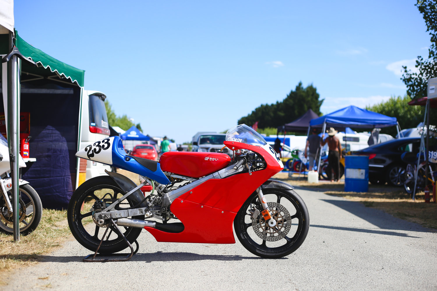
I took the RS50 out to Levels on the weekend for the Southern Classic and beat up some 250 4ts, 150 2ts and 150 4ts.
In race 2 I set the 4th fastest time of a grid of 35 bikes. Also got it up to 143km/hr with a wind break, ~136ish without. Pretty chuffed about... until I seized it at the fastest bit of the track and it put me in hospital with a bruised lung and coughing blood...
Well, your 50 is being well used Dave and even looked beautiful until we both ended up in the gravel.
http://www.grandprixmachine.com/blog...uthern-classic
Low personal B.M.E.P.
Might not, too....See ChrisC's report here...
Actually as i'm pretty sure I've already posted elsewhere, you could buy a little cable operated inlet tract/valve for your 100cc rotary valve kart engine back in the 60's. Pull the trigger for a burst of speed to pass....sounds like the Fan Boost for formula E cars now.
I'm pretty certain that you pulled the trigger at your own risk...
Chris - missed you again, dammit. At least you'll be moving slow enough for me to catch up and meet you now.
Forum whore
I'll bet they hated you, nothing worse than being beaten by a 50!
You need to get well soon and teach them that lesson again.
Low personal B.M.E.P.
No - not that kind of crowd. But anyone beaten by the Gixxer Cup bike that was there would be spitting tacks....
Forum whore
Welcome Johan. Your drawings are looking real nice. Why did you decide to build a 100 cc engine? Is there any form of competition you can use it in?
You may have seen the JBB-pictures I posted earlier, but in case you missed them, here they are once again.
If you wish to Google: JBB stands for Jean-Bertrand Bruneau, a French dentist with many original ideas about motorcycle chassis and engines.


No8 Wire Extraordinaire

Chris that is both good and bad to hear. Keep blowing into that machine with the floating balls and get those lungs sorted.
And go up a pilot size. Closed throttle is a swine on long tracks.
Don't you look at my accountant.
He's the only one I've got.
Hardcore Biker
Thanks for the pictures Frits
For several reasons one is that there is a 100cc class in drag racing here in Sweden. Another is that I'm lazy and I am working on a 50cc project to a friend so I can use some calculations from there.
After working with those little ones you cant stop being fascinated by how match you can beat them up. (It will be a variator engine)
Hardcore Biker
Muhr, can't exactly work out if the crankcases are separate or shared from the pics (others will probably point out the obvious) and make me look a blind wanker) but unlike the 'Rotax shared disc valve, where there was some symmetry, in your case, there must be some sort of asymmetry to the disc valve cavity and that there will be some preferential leakage favouring/disfavouring one cylinder. Could be so minor to be nothing anyway. Those Wobsssss and Fritsssss can advise here.
Also the disc valve appears to have a huge stress raiser in a non functional area at its hub. Nothing a couple of mouse movements couldn't sort out
Still, keep it going and look forward to seeing it converted to metal and noise.
"Success is the ability to go from one failure to another with no loss of enthusiasm.
Hardcore Biker
Yes,it's a divided crankcase
That's right, disk valve does not ned to look like that.
I'm curious if someone experienced a difference in terms of, getting of idle with a twin
Forum whore
I used to do the same thing at the old Taupo track on my 100 Bucket. (not the bruised lung part though).
Forum whore
Chris, sorry to hear you have had a bit of a nasty off, get well soon.best wishes from Team ESE for a speedy recovery.
Forum whore
.
Following on from Nath88’s suggestions about the amount of air flowing through the motor that needs fuelling depends on whether the motor has fired and the pipe action has sucked air through or not.
I have been looking for ways to see if the engine has fired or not. And I like Clints idea that measuring the in cylinder pressure just before exhaust port opening would be a reliable way to tell if the motor has fired. I guess it t would not take a very sophisticated pressure sensor to do that. One would not need to know the real pressure, only that there is more pressure and a simple home made sensor using a piezoelectric disk from a hobby shop may be enough to do that.
The system would not have to be that clever, with the help of an Aduino mini all I would need to know is that between two consecutive ignition trigger pulses there was an in cylinder pressure rise of a predetermined magnitude or not.
Clint Gray - www.tfxengine.com sent me some comments by email that made sense to me and with Clint’s permission I can share them.
The equipment that we sell is for engine tuning via measuring cylinder pressure, port pressure waves etc. per degree of crank rotation. That might be overkill for what you need.
There are 2 ways that you could do it in the cylinder.
The first would be to use a true cylinder pressure sensor which is necessarily exposed to the whole cycle. This would involve drilling and tapping the head.
The second way to do it would be to install a pressure sensor part way down the cylinder wall. It would involve drilling a tiny hole roughly 0.75mm to 1mm diameter straight into the cylinder wall then mounting a sensor somewhat back from the hole external to the cylinder.
As an example, if you drilled the hole anywhere in the cylinder wall circumference so the piston ring exposed the hole to the pressure from about 70 ATDC through all the crank angles to 70 BTDC, all you would need is a low pressure sensor mounted say an inch behind that hole (i.e. the hole is a 1 inch long passageway feeding the sensor), then take your reading at 80 ATDC and 80 ABDC. So twice per revolution 180 degrees apart. There would be quite a difference in pressure if the engine fired, yet the peak pressure and average temp the sensor would be seeing would not be all that high.
We also have a sensor that will work in the cylinder wall like described but it is super-fast etc. For what you are doing, if you mounted a sensor as above, the sensor would not have to be super-fast, nor would it see high pressures, and average temps wouldn't be all that high considering its location and the part of the cycle it is seeing. Also the hole is a dead end hole so there is no significant flow in that hole, not like a hole that is open to the atmosphere. You might be able to find/use a much cheaper sensor if you go through the cylinder wall.
Further to what I wrote above, regarding a small hole in the cylinder wall. As I mentioned you could measure twice per revolution 80 ATDC and 80 ABDC, or even just once per revolution at 80 ATDC and use a threshold pressure value to determine if it fired or not.
However, it would be simpler to take a reading at 80 ATDC and 80 BTDC then compare the two pressure values per revolution. That way you don't need to have a threshold pressure value, just compare the two directly every revolution, and since the readings are not 180 degrees apart, they are 160 and 200 degrees apart, it would be easy to know which reading is the ATDC reading and which is the BTDC reading.
The fact that the sensor is slow, say a ms delay shouldn't matter either. It is still going to "see" the pressure at 70 ATDC it's just that it's going to be a little bit of time for the sensor to fully register what it sees.
You will be able to tell right away whether you need to delay the reading a full ms or much less than that, because when the hole is closed the pressure the sensor is seeing is only going to be crankcase pressure, so not much, and then when the hole is uncovered it will jump up very quickly, to say 150-200 psi. A slow sensor may take a full ms to fully register a pressure to the nth degree but it will probably register most of that pressure rise in much less time than a ms. Lets say 200 psi is applied instantaneously to your ms delay sensor, well it may only take 1/10th ms for the sensor to register 50-100 psi of that 200 psi and that would be plenty to tell you that it fired. If you go this route use a sensor good for 300 psi or a little better so it has a safety factor.
If you run a small tube that seals (need good contact for heat transfer) to the engine, and it runs between the cylinder wall hole and the sensor, then the actual sensor (which is likely sizeable) can sit outside the engine where it has space. You still want the sensor fairly close to the engine of course.
FYI we have several customers that drill their cylinder walls and install one of our threaded M5 sensors, so it is not uncommon. They don't do it for the reason you are doing it for, they do it to more accurately measure cylinder pressures during the low pressure portions of the cycle. A low pressure sensor is used instead of a combustion sensor.
I think that you can still put a hole in at 70 ATDC and get a cheap and "slow" sensor to work. The average temperature from 70 ATDC to 70 BTDC is not going to be very high, and it's a dead end hole so not much flow.
With your 1/4"BSPT thread try to sleeve the inside hole of the sensor so that there is as little volume inside there as possible, without contacting the diaphragm in the sensor of course.
You want to have as little transfer of gases as possible moving to and fro, makes for less heat and a quicker fill (reading).
Clint.
There are currently 2 users browsing this thread. (0 members and 2 guests)
 Posting Permissions

 Reply With Quote
Bookmarks