Originally Posted by lohring

Thank you, interesting reading

 Hardcore Biker

Thank you, interesting reading
Hardcore Biker

Part by part, had an ambition to start it in 2018 but feels far away.
Forum whore

Looking good, Muhr.
But I would leave the red plastic parts out if I were you. You do not need the crankcase volume reduction, and what's worse, they are shrouding the big end bearings that need all the lubrication and cooling they can get. I would also remove the cover over the crankshafts: better for lube and cooling, and better for the flow of the mixture between the crank webs.
You are right about 2018 being far, far away. First we will have to eat ourselves through a shipload (I spelled that deliberately correct) of turkey and accompanying carbohydrates. But don't worry: it doesn't matter how much you eat between Christmas and New year, as long as you are careful between New year and Christmas.
Hardcore Biker
You're probably right, the plastic is 10.8cc a piece. I'm at about 263cc now TDC managed to get them very even with the offset disc.
I want some material on thecover left to make adjustments afterwards
Me and food have always been best friends
Highway Biker

Where you going to place the rotary valwe? At both case sides? Or modify crank disk in the middle...
Fair weather rider

Perhaps this is one of those out there, but anyone tried spraying metered amount of mixture to the ex port to extend pipe range?
Low personal B.M.E.P.
Does the engine then become a generator for a pulse jet ?
Fair weather rider
Was thinking more like simply adding heat for something like high compression ratio engine.
Hardcore Biker
Like this.
Hardcore Biker
I present you the work of a French tuner on exhaust pipe.
I translated the text as best as I could
Full version => http://as3-rdx-club.clicforum.fr/t90...DE-DETENTE.htmThe following graph shows the parent dimensions of the expansion pipe of several modern and efficient engines
the engines are very different:
- since a KX 500 1989, which must be rather progressive and having a modest relative power (for the cubic capacity)
- up to a Honda 125 RSR 1997 racing bike who makes 40 hp and who favors above all the maximum power
The shape of the pots is nevertheless very similar: the proportion of diameter (difference in diameter / deviation maximum diameter) as a function of the proportion of length (length / length "reference") follows almost always the same law:
- the position of the midpoint of the divergent is constant (68% of the reference length)
- the position of the midpoint of the convergent is constant (124% of the reference length)
- the length of the second half of the divergent is constant (25% of the length of the reference)
- the length of the first half of the divergent is at least (25% of the reference length)
- The length of the convergent is also constant (34% of the reference length)
- length of the right part (14% of the reference length)
The proportions in parentheses are an average of 35 engines, of which 10 are represented on the graph. This average is the red "reference" curve. These proportions are used to determine the dimensions of the pots afterwards.
It remains more to determine the length
I have complete information on 7 engines: all the dimensions, the curves of torque and power, the pressure readings in the exhaust:
On average, the peak of the pressure wave is formed at 1/10 of the exhaust time (thus 18 ° crankshaft after the opening of the exhaust (OE) for an exhaust of an opening time of 180 ° ).
After several tests of recipe, the "benchmark" constant of all these engines to wedge the motif of the pattern of pressures and depressions with that of the openings and closures of the port is the following: the cross between the depression and the pressure, which correspond at the rate of 10% before the closing of the transfers (FT) (10%: 10% of the transfer opening period). I give you a grace of physical interpretation. For those interested in it can talk about it more.
That is why I took as reference length, the length between the exhaust port and the center of the right portion (since the piston therefore, including the duct in the cylinder, the flange of the cylinder, the tube or elbow , the divergent and half of the right portion).
We know when the pressure wave is emitted (10% after OE), we know when it must return from the middle of the right portion (10% before FT). The formula for calculating the reference length, very simple from the desired speed and the speed of the wave, is written on the following page.
All of these values are set at the maximum speed power peak, because it is more available information and easier to use than another system. So the regime to take into account is the one wanted for the maximum power regime. If we want the maximum torque regime, it will be necessary to change the 10% (calculation to be done).
Highway Biker
Thanks Muhr. Me thinking about placing cylindrical rotary valve at medium of cranckshaft to both functions:
separate volumes
regulate intakes.
BTW I made Excel spreadsheet to calculate balance of 2-cylinder engines. At my case V2 90 generates 4 time less shaking force than just one half of V2.
I have rather short connecting rods L=73 for 40mm stroke.
Hardcore Biker
Do you know what crankcase volume the old gp 50 bike had like the Kreidler gp 50?
Thank Frits
Forum whore
I rather enjoyed that lecture, and it'll do your French some good as well. But we must remain critical, for example:So the most 'modern' engine in that lecture was a 20 year-old Honda that was 14 hp down on state-of-the-art power.The following graph shows the parent dimensions of the expansion pipe of several modern and efficient engines
- since a KX 500 1989...- up to a Honda 125 RSR 1997 racing bike who makes 40 hp
The outcome of any averaging will always be worse than the data of the best engine in the bunch. Sometimes averaging is sensible; sometimes it isn't .The proportions in parentheses are an average of 35 engines
Are we talking about the twelve-speed works Kreidler of 1960 or the Van Veen Kreidler of 1983, or somewhere in-between? Never mind, I have not memorized those values for the good reason that they all were too small.
The Aprilia-values that I know off the top of my head, may be more useful to you. The RSW125 had a volume of 650 cc at BDC, including transfer duct volumes, and the RSA had 675 cc. For a 50 cc that would work out as 270 cc. But if you are going to try that, you will also need porting and pipe efficiency as high as the RSA's....
Hardcore Biker
The article I present and translate is not mine.
I think interressant to share it here
Hardcore Biker
Really good information, I'm going to start a little shy, then go bananas! Getting up to the RSA level is probobly many peoples goal(dream). It's just that it's damn far away!!!
I was thinking of the Van Veen
There are currently 12 users browsing this thread. (1 members and 11 guests)
 Posting Permissions

 Reply With Quote
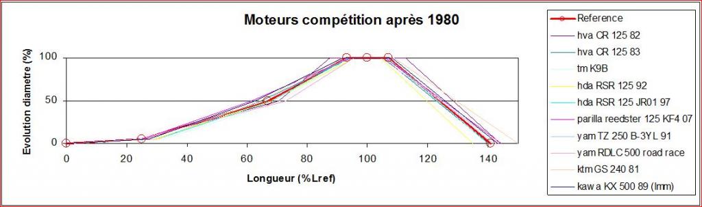

Bookmarks