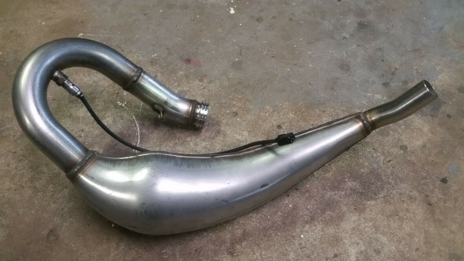
I have been trying to figure out a way of determining the relative air flow through my 2T motor.
From previous experience we know mass air flow meters don't work and that using the Ecotrons MAP sensor to measure the pressure in the crankcase or pipe just wound up with an average that slightly reduced below ambient as the motor came onto the pipe and flow through the motor increased.
I tried measuring the residual pressure pulse in the cylinder just before exhaust port opening. That worked well but did not tell me anything meaningful about air flow and fuelling requirements. Only whether the motor had fired or not. The best I could do with that information was to arbitrarily reduce fuel on the next cycle.
Attachment 335751
My new line of thinking is to use a pressure sensor and an Arduino to determine the difference between the maximum and minimum crankcase pressure each cycle and feed this value as a MAP signal to the Ecotrons EFI CPU for processing. I am picking this difference in pressures will be a good indication of mass air flow and therefor fuelling required.
Attachment 335754 Attachment 335753 Dyno runs taken in reducing 10% throttle position steps.
If the pressure difference idea works then I might be able to use the Volumetric efficiency VE map with the Ecotrons EFI system for the troublesome area below the 20% TPS region and the Alpha-N map for power. From experience I know that Alphan-N works well above 20% TPS.
Determining an indication of the mass air flow by finding the difference between maximum crankcase pressure as the piston descends and the minimum pressure as the pipe sucks the air/fuel mixture from the crankcase. This pressure difference must say something about the mass air flow and therefor the fuelling required, and I am guessing the pressure differential will follow the torque curve.
Hopefully, anyway if this does not work, there is always booze ....

Throttle held full open, TPS signal jerky green line.


 Reply With Quote


 . found some 9.5mm id elbows for the cyl and the Y and T, i made myself. weld a small bung on the rad top for the self bleeder hose is all that remains of the cooling system. machine the cyl decks flat and size the bore to the piston next week then ill be grinding the ports within two weeks im hoping


Bookmarks