Page 2129 of 2629 FirstFirst ... 1129162920292079211921272128212921302131213921792229 ... LastLast
Results 31,921 to 31,935 of 39427

Thread: ESE's works engine tuner

  1. #31921
    Join Date
    18th May 2007 - 20:23
    Bike
    RG50 and 76 Suzuki GP125 Buckets
    Location
    Auckland
    Posts
    10,479
    Click image for larger version. 

Name:	Wobbly TPS Signal Green Line.png 
Views:	77 
Size:	118.8 KB 
ID:	341972 Throttle held full open, TPS signal jerky green line.

    Two steps forward, one step backwards. Fixed a couple of things and then ran into this issue. A wobbly TPS signal. Hold the throttle full open and steady and the TPS signal jumps all over the place. Most noticeable when revs get up and it starts coming up on the power. I will have to sort this before I can progress to mapping the fuel table and seeing if the pseudo map simulator works like I hoped.

    Finaly seem to have sorted this (hopefully), simple really, tightened up all the terminals, who would have thought ......

  2. #31922
    Join Date
    18th May 2007 - 20:23
    Bike
    RG50 and 76 Suzuki GP125 Buckets
    Location
    Auckland
    Posts
    10,479
    Quote Originally Posted by oldjohnno View Post
    That's interesting - some time ago I was thinking about injecting fuel (methanol) up against the underside of the piston crown as a way of improving piston cooling. But I wasn't convinced the fuel would be sufficiently atomized and wondered whether the loss of cooling in the intake tract would cost power. I'm still tempted to give it a run on the dyno.
    I think squirting under the piston to aid piston cooling is a great idea. I tried that, although I was not able to get enough upwards angle to impinge directly on the under side of the piston crown I do think that the evaporating fuel mist helped with piston cooling. It certainly helped with fuel evaporation and smooth running. I even thought of locating the injector in the bottom of the crankcase so it had a straight shot at the underside of the piston.

    At low speeds just injecting under the piston worked well but at higher loads I had to also inject in the B ports just to be able to get enough fuel in there. I was also worried about loss of power due to the loss of inlet cooling but in the end I did not notice any power difference to carburation. In fact I made a little more power with injecting. Probably because I was able to more accurately adjust the fuel curve.

    Click image for larger version. 

Name:	EFI Under Piston Injector.JPG 
Views:	85 
Size:	134.2 KB 
ID:	341974Click image for larger version. 

Name:	EFI Piston Slot.jpg 
Views:	101 
Size:	231.0 KB 
ID:	341975Click image for larger version. 

Name:	B port injection against the air flow.jpg 
Views:	89 
Size:	788.6 KB 
ID:	341976Click image for larger version. 

Name:	Under piston injection.jpg 
Views:	100 
Size:	748.9 KB 
ID:	341973

  3. #31923
    Join Date
    19th June 2011 - 00:29
    Bike
    KR-1S, KR1-SV, KXR500, ZXR 4/600
    Location
    Belgium
    Posts
    270
    Quote Originally Posted by TZ350 View Post
    Attachment 341970 Air Cooled and Fuel Injected Suzuki GP125
    This way I can have the best of both worlds. Alpha-N which has proved reliable and very tune-able when the motor is on song and responsive variable fueling at lower throttle openings.

    Combining the two mapping typologies, Alpha-N and VE should be relativly easy with the Arduino Nano pseudo MAP system. Below 45% I make the output variable and above I make it fixed at atmospheric.
    shouldn't the ideal point for switching be the rpm at which the pipe begins to work, and not throttle opening ?

    comming out of a corner with throttle at 60% within the pipe rpm surely needs different variables than below the pipe's rpm I would thinck ?
    Or are you solely looking at it from a racers pov, i.e. you are not supposed to leave the working range of the pipe ?

  4. #31924
    Join Date
    3rd May 2017 - 04:03
    Bike
    1997 Yamaha rd 350
    Location
    Russia
    Posts
    171
    Quote Originally Posted by Grumph View Post
    That sounds a lot like Hilborn injection with the pump speed/output electronically regulated. I'm assuming from your description it's constant flow ?
    Probably this patent close to reality. Cannot be sure.
    https://patents.google.com/patent/US9534528B2/en

  5. #31925
    Join Date
    18th May 2007 - 20:23
    Bike
    RG50 and 76 Suzuki GP125 Buckets
    Location
    Auckland
    Posts
    10,479
    Quote Originally Posted by JanBros View Post
    shouldn't the ideal point for switching be the rpm at which the pipe begins to work, and not throttle opening ? coming out of a corner with throttle at 60% within the pipe rpm surely needs different variables than below the pipe's rpm I would think ? Or are you solely looking at it from a racers pov, i.e. you are not supposed to leave the working range of the pipe ?
    Interestingly Alpha-N works well at all throttle settings below the rpm where the pipe works but I guess not a surprise as air flow there is consistent.

    So you are right, confining the VE table to less than 45% TPS and only in the RPM range where the pipe is expected to be working should be the aim. Because that is the area where airflow is variable.

    In my experience if the motor is firing, then above 45% the airflow becomes increasingly consistent within the full range of rpm and Alpha-N can do the job very well.

    Agreed, I will probably need to use both TP position and "RPM" to select the switch point between Alpha-N and VE. Just to limit VE only to the lower TP, say less than 45% TPS at higher RPM where the pipe is working. Every where else can be Alpha-N.

  6. #31926
    Join Date
    18th May 2007 - 20:23
    Bike
    RG50 and 76 Suzuki GP125 Buckets
    Location
    Auckland
    Posts
    10,479
    .
    Had the bike back on the dyno again today. Simulated the blast up the straight, roll off the power and gently back on again. Like you would negotiating a corner. I did this a few times at the sort of rpm you would be using on the track.

    It showed real responsiveness and actually looks like it is working. Mapping is a bit crude and the motor needs some maintenance. So I will strip the motor and spruce everything up then get onto mapping the fueling properly.

    Anyway it looks very much like the Delta Crankcase pressure idea is the answer to keeping track of changes in airflow through a single cylinder high performance two stroke EFI motor.

    KTM, we worked out how it is done and successfully tested it. Now the world knows the secret to fuel injecting a high performance two stroke, (EFI 2S) too.

    KTM's disapproval of our work ...... Click image for larger version. 

Name:	KTM.jpg 
Views:	61 
Size:	52.2 KB 
ID:	342019

  7. #31927
    Join Date
    18th May 2007 - 20:23
    Bike
    RG50 and 76 Suzuki GP125 Buckets
    Location
    Auckland
    Posts
    10,479
    Quote Originally Posted by TZ350 View Post
    I have been trying to figure out a way of determining the relative air flow through my 2T motor.

    From previous experience we know mass air flow meters don't work and that using the Ecotrons MAP sensor to measure the pressure in the crankcase or pipe just wound up with an average that slightly reduced below ambient as the motor came onto the pipe and flow through the motor increased.

    I tried measuring the residual pressure pulse in the cylinder just before exhaust port opening. That worked well but did not tell me anything meaningful about air flow and fuelling requirements. Only whether the motor had fired or not. The best I could do with that information was to arbitrarily reduce fuel on the next cycle.

    Attachment 335751

    My new line of thinking is to use a pressure sensor and an Arduino to determine the difference between the maximum and minimum crankcase pressure each cycle and feed this value as a MAP signal to the Ecotrons EFI CPU for processing. I am picking this difference in pressures will be a good indication of mass air flow and therefor fuelling required.

    Attachment 335754 Attachment 335753 Dyno runs taken in reducing 10% throttle position steps.

    If the pressure difference idea works then I might be able to use the Volumetric efficiency VE map with the Ecotrons EFI system for the troublesome area below the 20% TPS region and the Alpha-N map for power. From experience I know that Alphan-N works well above 20% TPS.

    Determining an indication of the mass air flow by finding the difference between maximum crankcase pressure as the piston descends and the minimum pressure as the pipe sucks the air/fuel mixture from the crankcase. This pressure difference must say something about the mass air flow and therefor the fuelling required, and I am guessing the pressure differential will follow the torque curve.

    Hopefully, anyway if this does not work, there is always booze ....
    March 17/2018 This is my original post where I first talked about looking at Delta crankcase pressure as a way of tracking air flow changes through a two stroke motor. Hopefully it predates any of KTM's efforts at Patenting the concept. Like Flettners "B" Port injection, it would be good to be able to keep it all out in the public domain and available for anyone to use.


    A couple of other threads that are worth looking at if 2S EFI is your thing.

    https://www.kiwibiker.co.nz/forums/s...2T-EFI-Project

    https://www.kiwibiker.co.nz/forums/s...agement/page15

  8. #31928
    Join Date
    20th April 2011 - 08:45
    Bike
    none
    Location
    Raalte, Netherlands
    Posts
    3,342
    Maybe not the place for it, I take the liberty of posting it here anyway:
    Click image for larger version. 

Name:	Happy Birthday Jan Thiel.jpg 
Views:	41 
Size:	114.1 KB 
ID:	342020

  9. #31929
    Join Date
    18th May 2007 - 20:23
    Bike
    RG50 and 76 Suzuki GP125 Buckets
    Location
    Auckland
    Posts
    10,479
    .
    Happy Birthday Jan......

  10. #31930
    Join Date
    20th January 2010 - 14:41
    Bike
    husaberg
    Location
    The Wild Wild West
    Posts
    11,832
    Click image for larger version. 

Name:	Jan Cake.jpg 
Views:	38 
Size:	196.7 KB 
ID:	342021 Click image for larger version. 

Name:	Thiel superman.jpg 
Views:	39 
Size:	23.5 KB 
ID:	342022As above Jan thanks.......
    Quote Originally Posted by Katman View Post
    I reminder distinctly .


    Kinky is using a feather. Perverted is using the whole chicken

  11. #31931
    Join Date
    8th February 2007 - 20:42
    Bike
    TZ400
    Location
    tAURANGA
    Posts
    3,895
    Frits , this is for sure the place to say Happy Birthday to the man that has been, and always will be the biggest inspiration
    to us " young fella's " in the world of 2S tuning.
    I salute you Jan Thiel , and hope you have a happy day with your family and friends.
    Ive got a thing thats unique and new.To prove it I'll have the last laugh on you.Cause instead of one head I got two.And you know two heads are better than one.

  12. #31932
    Join Date
    27th October 2013 - 08:53
    Bike
    variety
    Location
    usa
    Posts
    942
    happy bday jan. for sure you are a inspiration to me and I think all your work is excellent


    got a bit more done guys. all the water piping is mostly complete but I haven't a clue what im doing so who knows if its any where near correct . found some 9.5mm id elbows for the cyl and the Y and T, i made myself. weld a small bung on the rad top for the self bleeder hose is all that remains of the cooling system. machine the cyl decks flat and size the bore to the piston next week then ill be grinding the ports within two weeks im hoping
    Attached Thumbnails Attached Thumbnails Click image for larger version. 

Name:	Resized_20190602_180819_260.jpeg 
Views:	96 
Size:	215.7 KB 
ID:	342023  

  13. #31933
    Join Date
    1st May 2016 - 13:54
    Bike
    Vintage 2T
    Location
    Brisbane
    Posts
    435
    Happy Birthday Jan.

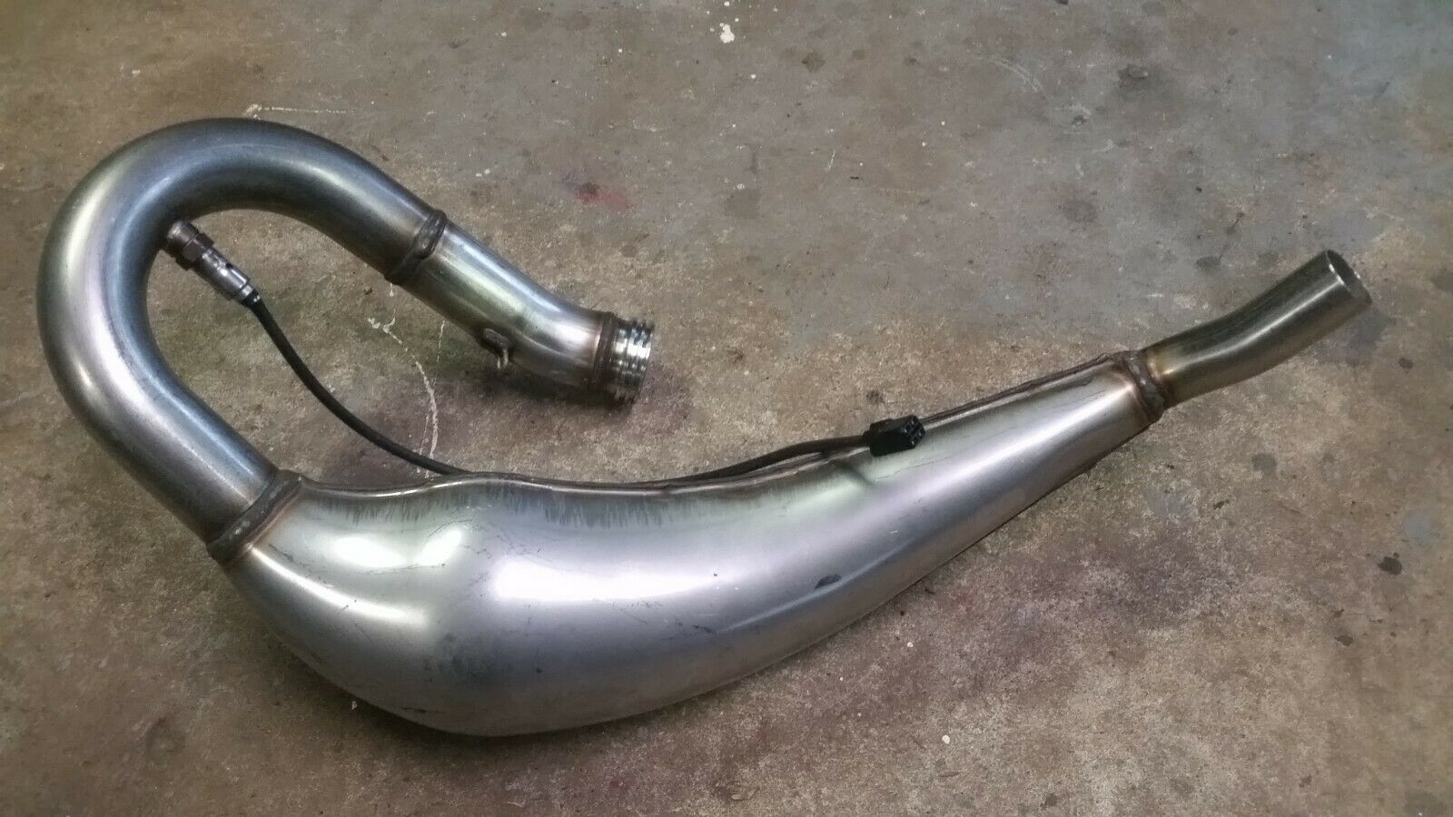
    Re: KTM TPI, here is what the exhaust looks like.


    I assume the extended parallel header is to keep up the heat and pressure to deal with the CAT.

    Cheers, Daryl

  14. #31934
    Join Date
    18th May 2007 - 20:23
    Bike
    RG50 and 76 Suzuki GP125 Buckets
    Location
    Auckland
    Posts
    10,479
    .
    Thanks for the picture of the pipe, some interesting features. A cat converter?

  15. #31935
    Join Date
    18th May 2007 - 20:23
    Bike
    RG50 and 76 Suzuki GP125 Buckets
    Location
    Auckland
    Posts
    10,479
    Click image for larger version. 

Name:	AN vis VE.png 
Views:	58 
Size:	345.6 KB 
ID:	342035

    This is how I would setup the EFI fueling using the delta crankcase pressure concept.

    The Red area below 45% TPS and in the RPM area where the pipe is working I would setup the fueling for VE volumetric efficiency. MAP vis RPM.

    Every where else in the Green area I would setup fueling as Alpha-N. TPS vis RPM.

    And in the Purple area below the RPM where the pipe works and TPS = 0% the MAP value needs to be set at 0.2 - 0.4 bar. This is necessary because when the pipe is not sucking strongly the crankcase pressure rises to someplace close to 0.8 - 0.9 bar of dirty air. This happens because the pipe is not drawing airflow through the motor and atmospheric pressure and stale exhaust gasses flow back into the crankcase raising the pressure there and in the inlet tract.

    The motor can idle with a crankcase full of dirty air because some fresh air/fuel makes its way through the smog and randomly finds its way into the cylinder. At idle the cylinder has some fresh air and a lot of smog.

Thread Information

Users Browsing this Thread

There are currently 144 users browsing this thread. (0 members and 144 guests)

Posting Permissions

  • You may not post new threads
  • You may not post replies
  • You may not post attachments
  • You may not edit your posts
  •