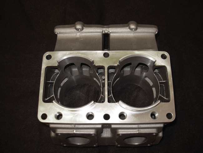
Yes , two of the channels are inline longitudinally , bottom to top on the angled cylinder , the other two are offset to line up with the rotated water exit.
The blind holes are offset outward slightly so as to maintain the stock insert step that keeps water away from the chamber area.
Note also that the top of the step is recessed slightly , to give an air gap for even more heat path insulation.
Ive got a thing thats unique and new.To prove it I'll have the last laugh on you.Cause instead of one head I got two.And you know two heads are better than one.
Yes , two of the channels are inline longitudinally , bottom to top on the angled cylinder , the other two are offset to line up with the rotated water exit.
The blind holes are offset outward slightly so as to maintain the stock insert step that keeps water away from the chamber area.
Note also that the top of the step is recessed slightly , to give an air gap for even more heat path insulation.
Am I correct in thinking the coolant flow path is through the crankcase then entering the cylinder to one side and above the exhaust port and then out through the head? Is the coolant directed around the exhaust duct in any way or is there just a pool of coolant around the whole duct? Asking because I wonder if the coolant below the exhaust duct actually circulates much or is a stagnant pool. I can see from Googled images that the flow through the head cover and insert is biased to flow from the intake side to the exhaust side by the inlets in the cover and then out. I cannot find a cutaway view to tell if any coolant flows over the combustion chamber in a stock setup or if it only flows around the outer diameter of the bore in the head cover.
The water below the exhaust duct stops being stagnant if you drill two 3.5mm holes thru the case and thru the dimple recesses in the cylinder on an R1.
In the C model ( and older ) drill the holes thru the alloy blanking plugs in the case , and knock them out of the cylinder.
This way a small amount of water is directed out from under the duct - helping to cool it.
But nowhere near as much as it was done originally with all the water coming out of the case - up under the duct ( where it then became hot ) and overheated the transfers.
Ive got a thing thats unique and new.To prove it I'll have the last laugh on you.Cause instead of one head I got two.And you know two heads are better than one.
Is the notion of running coolant close to the sparkplug threads no longer the prefered design?
Wobbly - Thanks again for sharing from the bag of tricks! I logged in to ask a question about the insert, but low and behold, I get to the bottom and Larry already asked it. I'm curious about cooling the plug as well.
I spent ages trying different methods to get water into the squishband area , without cooling the chamber as well.
This proved hard enough , but trying to do that as well as cooling the thread area , proved impossible to do efficiently without cooling the back side of the chamber as well.
Even with the large mass of alloy around the threads , the straight line ignition creates deto in the squishband , well before the plug body overheats and blows a hole thru the piston.
So in this application ( KZ ) the head makes more power , keeping water away completely from around the rear chamber area.
In other very high bmep engines with "proper " ignitions overheating the plug body does seem to be the limiting factor and these certainly benefit from thread cooling.
Ive got a thing thats unique and new.To prove it I'll have the last laugh on you.Cause instead of one head I got two.And you know two heads are better than one.
I spent ages trying different methods to get water into the squishband area , without cooling the chamber as well.
This proved hard enough , but trying to do that as well as cooling the thread area , proved impossible to do efficiently without cooling the back side of the chamber as well.
Even with the large mass of alloy around the threads , the straight line ignition creates deto in the squishband , well before the plug body overheats and blows a hole thru the piston.
So in this application ( KZ ) the head makes more power , keeping water away completely from around the rear chamber area.
In other very high bmep engines with "proper " ignitions overheating the plug body does seem to be the limiting factor and these certainly benefit from thread cooling.
Could you use the insulating paint to control the areas exposed to the coolant it will not stop conduction through the aluminium but it might help, Almost like your ceramic coating of the chamber only more easy to do in the inner head cover?
Kinky is using a feather. Perverted is using the whole chicken
Selachii 2 stroke carburetor. This obscure piece of 2 stroke history you have never heard of was invented in Vancouver Canada. It doesnt have a float bowl and the entire carb is made from plastic. Manufacturing started in 1978 and it uses a proprietary GE plastic called Valox 420. It has no jets and about 18 parts and that's including the screws that hold it together. One plastic needle inside the emulsion tube is the only thing that adjusts fuel. The slides are on a gear rack and open simultaneously
it seems work as a Gardner Lectron Possi Lake etc in that it works of a needle and taper and shape has no float bowl like a lake injetor so will need a vacuum tap or a good memory to turn off the fuel.
but the venturi and bore opens on both sides this seems pretty cool.
Edit Although in this design it appears the needle runs inside an atomizing tube all the time? not sure why this is needed?
If looks could win races they would do alright
Kinky is using a feather. Perverted is using the whole chicken


 Reply With Quote


Bookmarks