I would like to know more about these percentages, and how they relate to pipe design philosophy in general.Originally Posted by wobbly


 Forum whore

I would like to know more about these percentages, and how they relate to pipe design philosophy in general.
Bogeyman

I'm hugely relieved to hear you say that, the numbers some of my designs produce come nowhere near what I intended.
Go soothingly on the grease mud, as there lurks the skid demon
Weekend cruiser

ah this might explain why I am still having such big startup issues with the ignitech... Now running a battery to make starts easy.
Wobbly do you know what the powerjet settings look like on a stock yz250 in terms of on/off rpm and tps?
Forum whore
Not quite, Pugs. Engine breathing capacity is not expressed in port area but in angle.area. For example you can have a transfer port, 1 cm wide and 1 cm high, so it has an area of 1 cm². If that same port is situated 1 cm higher in the cylinder, it will still have the same area, but it will have a much longer open timing, so there is more time available for flow through that port.
Identical angle.areas will give identical achievable power, but that need not happen at identical rpm. If an engine has twice the cubic capacity it will take twice the time to scavenge it through a given angle.area. That means it has to rev twice as slowly, or it will not be completely scavenged.
The ratio (angle.area divided by cubic capacity) is called specific angle.area. And specific angle.area divided by rpm is called specific time.area.
To summarize: specific time.area is port area, multiplied by the time during which it is open, per cc.
Reciprocating mass limits the maximum safe rpm that the crankshaft will tolerate. Specific time.area limits the maximum rpm at which the cylinder can still be completely scavenged.
Forum whore
If I were to explain pipe design I would need to write a book,but in general things are pretty straight forward in relation to the % values.
End of header is always 31 to 33% and end of diffuser is always 62 to 68%.
To see the effect of a silly long header, you can watch the pressure ratio at the Ex port, and thus the effect this has on the depression in the cylinder.
We are looking for the lowest and widest negative ratio we can get around bdc when the transfers are fully open.
A long header delays the beginning of the depression too late in the cycle, when in the power band.
In a race 2T we are always fighting power range Vs peak power.
Shorter diffusers create steeper angles,thus greater wave amplitude, but this narrows the effective band width.
So - in general the best compromise is around 66%.
Ive got a thing thats unique and new.To prove it I'll have the last laugh on you.Cause instead of one head I got two.And you know two heads are better than one.
L-Plate Rider
Gentlemen, I'd just like to poke my nose in here and say that I've been lurking in this thread for quite some time and it just keeps getting better and better. By far the most informative thread I've found on 2 stroke design. Thanks to all and keep at it. As a guy who plays with 2 strokes as a (very expensive) hobby, I really appreciate everything openly posted here. The fellow who rides the race RZs I build thanks you too.
Weekend cruiser
i'd pay a premium for that... seriously. But I know the economics of it aren't good.
Forum whore
A well-played violin can be poignant. Do you know what is even more poignant? two violins.
It's the same with engines. Playing with 2 strokes can be an expensive hobby. Can you guess what is even more expensive?
L-Plate Rider
oops, double posted
L-Plate Rider
LOL. Fair enough Frits, thats some perspective. Expensive is relative of course. In the last couple of months I've bought a TD2 project bike, a TZR250 for one of my projects and more parts and services bike related than my marriage could stand were it openly discussed.
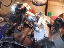
In the spirit of the co-operation already in this thread, and considering that fuel injection was brought up earlier, here is the beginning of a prototype system I've been playing with. I'd appreciate any feedback, hopefully productive. If you'd like to say it won't work that's fine but please explain why?
Now some of you may recognize my name as a member of another forum where FI has been discussed,(I recognize some of your usernames), and may hold against me some things I said there. Please understand that my comments there were made because of my frustration with a poster there and his apparent arrogance and unwillingness to share information. Don't misunderstand me, I don't believe that it was required of him, but rather than refuse to answer questions he acted as though the questions were somehow beneath him. I would appreciate it if these pics didn't appear elsewhere. I'd rather it be running before I face the firestorm. Thanks.
edit. I really don't know why those pics are so small...sorry
Forum whore
My bet is ...... BikerChick
Bucket Racer/Crasher
2 strokes and good looking women . . . I'm willing to pay the cost.
Re the FI above, the idea looks good but I have serious reservations about the manifold. I would have thought a nice tuned length velocity stack arrangement for each cylinder into an airbox with the injector mounted overhead would flow better. TZ has shared quite a bit of info about what has improved the flow through his carbs. I'd be tempted to even go for some sort of nozzle/venturi leading to the reed cages to create a high velocity section. It could be a good tuning enhancement, you could change it's location and dimensions depending on results. It could even be made variable easily. I'm sure you have already done it but there is good gains to be had by filling in the reed cages and keeping the cross-sectional area constant or tapering slightly to the reeds. What management system are you using?
Scooter boy

New electronic carb by dellorto http://www.dellorto.it/ecs.asp you may need to change it to english
Forum whore
If Wiseco is your thing ....
New Zealand supplier in Auckland of Wiseco rings, sleeves and piston kits.
http://www.sportspro.co.nz/products/...eco_rings.aspx
Hardcore Biker

Wob, those percentages are refering to the tuned length of the pipe? Transition nozzles/flanges at the beginning should be taken into account? - you refered to end of parts, that's why I'm asking.
There are currently 10 users browsing this thread. (0 members and 10 guests)
 Posting Permissions

 Reply With Quote
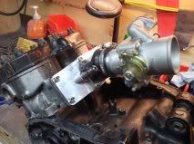
Bookmarks