1 mm should be enough to avoid the viscous drag.Originally Posted by twotempi


 Forum whore

1 mm should be enough to avoid the viscous drag.
Forum whore
Wob, I assume you are reacting to my remark" I can hardly imagine the blowdown time.area will allow for more than 9000 rpm. That means: any more revs and the hot exhaust gases will blow down into the transfer ducts".
Vannik's EngMod2T sim calculates the mass of fresh charge that can make it into the cylinder through the fraction of the transfer STA that remains available after the blowdown phase has ended. And I think EngMod2T is an excellent design tool. But I use a different approach: my sim calculates the blowdown STA that is required if you want to avoid any exhaust gas entering the transfers.
Your screenshot shows a BMEP of 11.4 bar @ 12,500 rpm. That is, like you say, achievable and believable. The Aprilia RSA also develops its maximum BMEP at about 12,500 rpm, but its value is almost 50% higher. You cannot keep an engine like that thermally sound if you allow any exhaust gas to heat up the cylinder, hence the different starting point in my STA calculations.
Granted, if the engine produces less power, you may get away with some blowdown into the transfer ducts. I merely tried to indicate that you can combat cooling problems by paying attention to the blowdown STA.
Forum whore
It has been a very long time since I experimented with Gordon Blair's originial EngMod program and I have no hands-on experience with Vannik's latest development, so maybe I am stating the obvious. But I think it could be interesting to investigate how a sim handles blowdown time.area.
In a real engine the exhaust gas defines how much time.area it needs to leave the building. If the transfer ports open before the cylinder pressure has fallen below the scavenging pressure, the exhaust gas will regard those open transfers as yet another set of exhaust ports and it will enter the transfer ducts. That will steal some of the transfer time.area.
Then, when the cylinder pressure has dropped sufficiently, those exhaust gases have to be expelled from the transfer ducts; that steals some more transfer time.area before the real transfer of fresh charge can commence.
So when an engine revs too high for the available blowdown time.area, it is the remaining available transfer time.area that suffers doubly. That is also the reason that power drops rather steeply past its maximum.
Now a sim must calculate the necessary blowdown TA and subsequently it can either calculate the remaining transfer TA, or it can calculate the total transfer TA and take into account that transfer can only start once the pressure ratio from transfers to cylinder is > 1 and that any exhaust gas must be washed out of the transfer ducts before fresh charge can start its journey into the cylinder.
It all boils down to this: if you reduce the exhaust timing or exhaust port width in a sim, does that result in a decreasing transfer time.area? Please let me know.
Forum whore
The raw numbers as presented in the STA calculations take no account of possible backflow issues with insufficient blowdown.
All that is reported is the ability ( or otherwise ) of the entered port and timing geometry to make "X " amount of power.
Obviously it is up to the practitioner to ensure that the relationships between the various STAs for each port set will work synergistically.
As we have discussed on other forums the Blow STA is all important - but the Trans STA must also reflect the port/duct geometries ability ie its CD - to flow air to the level expected.
ie a port as described to the sim may be capable of say 50 Hp, but if it has a parallel sided duct with no inner radius then one must spec a much higher Hp port for it to actually flow enough
to achieve the desired amount in reality.
The sim on the other hand fully accounts for the differential across the transfer port,be this + or - to create inflow or outflow.The only issue that it cannot deal with is the scavenging pattern changes
created by blowdown affecting the first port to open,causing this staggered high port to flow last.
We can describe the general effects by changing the scavenging model input, but changing the timing of one port,is only seen as a change in area/timing, and thus a change in the blowdowns effect on flow - not as a change in scavenging efficiency.
Thus the sim uses the bulk flow created by the pressure ratio conditions,and all of the inflow/outflow and pressure differentials are shown during the sim running and any can be plotted in post analysis as needed.
Neels can add more to this if he feels the need.
Re the GP125 sim, I was alluding to the fact that I pushed the single Ex port scenario to its limits with as wide and as high timings as I dared go,then matched the transfer capabilities to this.
The closer the cylinder gets to having optimum transfer geometry, with the numbers shown in the STA file,then the closer it will come to meeting those theoretical upper limits.
Right now, I would suggest that the correlation is very very good,when you look at the mechanical parts and the limitations set by the 24mm carb.
It was the raw STA numbers that pointed the direction to go - and the sim proved it was possible.
On the dyno it went from 28 to 31 Hp by following the sims lead - now all it needs is more port duct massage, and a good pipe.
The limiting factor in the STAs is the intake - it says around 37 CHp, so Im sure if the other improvements are made, it can make the rear wheel of around 33 RWHp this implies.
One thing that cannot be quantified is how much the heating effect of the blowdown reverse flow is able to be dissipated by the cooling fins.Rob says it was fine at 28 Hp.
Only way to see if the engine is now on the limit is to thrash it do death on the dyno, emulating as far as possible the air flow regime with a fan, and see if the power fades dramatically.
A direct drive KT100 will fade 3 Hp in 18 after 4 pulls from 6,000 to 16,000 in 9 secs,change the pipe and loose a couple of that peak Hp and you can run all day with no fade at all, but still see the same 620C on the egt.
Ive got a thing thats unique and new.To prove it I'll have the last laugh on you.Cause instead of one head I got two.And you know two heads are better than one.
Forum whore

Thats very interesting, I have been looking at what you and Wob have had to say, plenty of food for thought there.
The engines STA's, exhaust port and 31rwhp graph
No8 Wire Extraordinaire
Ooeer that's a very big square one (said the bishop to the hermaphrodite).
Don't you look at my accountant.
He's the only one I've got.
Forum whore
Did you notice the devcon in the front transfers to get the roof angle and timing right?
Anorak
Question One. "Was running is not confidence inspiring start"
Question Two Who is Jimmy?
Question Three the Honda rod you are running was designed to hold 11hp and there is i believe a modded one that only dynos this now.
The GT250a/m has a little bit more (with the same rod) than 12hp/cylinder so i guess they may have over engineered it a bit in reserve anyway. (I bloody hope so)
connecting rod Aprillia GP-125.
Overall length 147.20 mm.
Width little end 15.00 mm.
Hole diameter the minor end 19 mm.
Width 15.00 mm thick end.
The crank pin 20 x 49 mm.
Bearing silvered 20x33x1 mm.
Hole diameter Big end 26 mm.
Connecting rod center hole interval 115 mm.
Little end bearing cage silver 15x19x19, 40 mm
Storändans stock basket silver plated with 15 pins, width 14.75 mm
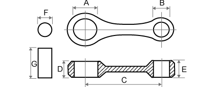
MODEL
B-100P/B-120 W/W
OEM No. -11001
CODE No. BS0200B
B.E.BEARING DIA (mm):A 26.00
S.E.BEARING DIA (mm):B 18.00
B.E.& S.E. PITCH (mm):C 110.00
B.E.THICKNESS (mm):D 17.00
S.E.THICKNESS (mm):E 17.00
CRANK PIN DIA (mm):F 20.00
CRANK PIN LENGTH (mm):G 20.0 X 49.0
STROKE 2
CON,ROD CODE No. CS0240X
MODEL
GT-250A/M W/W
OEM No. -11001
CODE No. BS0400B
B.E.BEARING DIA (mm):A 26.00
S.E.BEARING DIA (mm):B 18.00
B.E.& S.E. PITCH (mm):C 110.00
B.E.THICKNESS (mm):D 17.00
S.E.THICKNESS (mm):E 17.00
CRANK PIN DIA (mm):F 20.00
CRANK PIN LENGTH (mm):G 20.0 X 57.0
STROKE 2
CON,ROD CODE No. CS0240X
But yeah you can say I told you so if.
Only If it is ever completed and ever snaps a rod.

Kinky is using a feather. Perverted is using the whole chicken
No8 Wire Extraordinaire
Probably still in there, but he hasn't raced for some years. Used to be the fastest 100 about.
A snapped rod cuts the cases in half leaving nothing salvageable bar the gearbox & puts you on the ground quicker than you can think.
Don't you look at my accountant.
He's the only one I've got.
Anorak
My father snapped a rod at Southbridge while i watched. the Rod snapped in 1992 ish and he still limps.
The engine is still on the bench as a reminder, the crankcases and crankshaft are unscathed the barrel and piston head are not so nice.
A virtual choc fish i anyone can figure out what model of bike it was?
Hint 250 single four stroke eccentric adjustable tappets, aluminum alloy Rod, shell bearing big end.
Grumph is excluded. As he will know straight away.
Last edited by husaberg; 29th March 2012 at 19:05. Reason: Kickaha should be excluded as well because it never dropped a valve
Kinky is using a feather. Perverted is using the whole chicken
Low personal B.M.E.P.
So do what i do with the TKRJ four stroke rods....clean up & remove forging flash, radiusing etc where experience says it's good.
Polish - I get a pro polisher to do this bit.
Then shot peen. Aviation Support services or similar guys servicing the aircraft repair sector are good & fairly cheap.
In the riders seat

Matchless G2 ?
"If you can make black marks on a straight from the time you turn out of a corner until the braking point of the next turn, then you have enough power."
Anorak
Check the rules
But no
The G2 rod is neither shell and the rod is not aluminium alloy is it?

Kinky is using a feather. Perverted is using the whole chicken
In the riders seat
Dunno, didn't bother checking I just knew some of the AMC lot used eccentric adjusters
Sort your fucking post out to would ya
I should just look up the program
"If you can make black marks on a straight from the time you turn out of a corner until the braking point of the next turn, then you have enough power."
Bucket Racer/Crasher
Jim has a B120 rod. Supposedly it's OK, the problem is the B120 BE bearing which is utter crap. Jim's motor only just wakes up at probably 11,000rpm and revs heaps beyond that. With the RGB pipe it hits pretty hard as well but is fine if you keep it over the point where it transitions onto the pipe. The poor old bearing was never designed for that.
There are currently 53 users browsing this thread. (0 members and 53 guests)
 Posting Permissions

 Reply With Quote
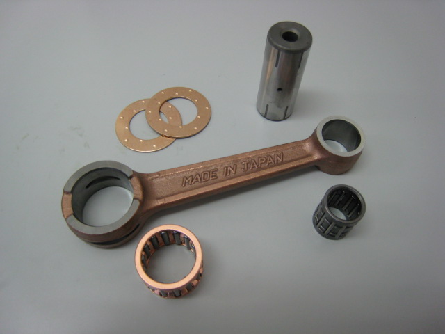


Bookmarks