http://www.dynamometer-info.co.uk/diy-dynamometer.htm
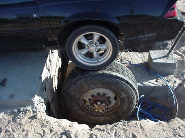
A really heavy roller or drum(s) - This needs to be heavy enough to give a long enough period with even a really powerful car or bike to allow fuel flow, boost etc to stabilize properly. It also needs to be 16 inches diameter or above to prevent losses, tyre damage, and maximise traction to give good accuracy. It must be very free running, and of a known (mathematically calculated) inertial value. This needs serious consideration and testing to find the best size and mass. Our own Motorcycle one for example, finished up at 402mm Diameter x 562mm wide and solid turned steel.
(weighs 2/3rds of a ton) Two of these are fine for up to 600 or 700 BHP cars as well. This gives almost twice the inertial value of the then popular DynoJet Dynamometer for bikes. And about 3 or 4 times as much as some current "dynamometers"! Smaller diameter = tyre slippage, and frictional losses, Smaller width = not enough load to fully test powerful drag bikes or to load up even modern stock bikes in lower gears.
A Computer interface timing card / board, to accurately measure both engine RPM and time each drum revolution to a VERY high
degree of accuracy. This level of accuracy must be far more precise than a computer or soundcard at 44k sample rate could ever achieve! There are many Dynamometers out there that use the computer to time the drum! They do NOT work accurately enough, and because of this need to use lots of data averaging on the graphs, This is very obvious when you look at the number of data points plotted on the screen on some so called "dynamometers"... The data they produce is pretty useless. This data card part is difficult - much more so than you could ever believe. Its also why the majority of small companies Dynamometers do NOT read real time RPM data during the run, as well as needing to use a HIGH level of data averaging in their graphs... This disguises the real issues, but stops you from seeing what really did happen during the run! BE VERY CAREFUL! This applies to a lot the inertia Dynamometers sold! Unless you are an electronics expert, and also a programmer they you are going to need to find one! If you get a dyno graph print out that gets more spiky in taller gears, and at the top "high power part of the curve, be very suspicious!
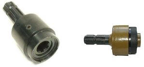
A Drum sensor! Sounds easy but the timing accuracy required is far greater than at first glance would seem to be required! A simple hall effect device or a shaft encoder is NOT accurate enough. A gear position, dual hall effect latching sensor is, provided you are looking only at a single point (every 360 degrees) point on the drum.
A Computer... cheap, buy anywhere!
Some dyno software! Mine took 3 years of development and rewriting to finally get everything right and as we needed, with database, auto graph scaling, etc. Be warned, its easy to produce a graph, MUCH harder to produce a final finished useful bit of software with all the facilities you actually need! If you are not good with C programming, and physics, forget it!
A dyno chassis to mount the car / bike / drum(s) into! This is obviously the easiest bit by far!
Stuff like cooling fans, exhaust extraction, gas analysers, etc too, but technically these are not really part of the dyno system.


Originally Posted by Yow Ling


 Reply With Quote


Bookmarks