Page 625 of 2704 FirstFirst ... 12552557561562362462562662763567572511251625 ... LastLast
Results 9,361 to 9,375 of 40555

Thread: ESE's works engine tuner

  1. #9361
    Join Date
    18th May 2007 - 20:23
    Bike
    RG50 and 76 Suzuki GP125 Buckets
    Location
    Auckland
    Posts
    10,516
    Click image for larger version. 

Name:	130 mm.jpg 
Views:	86 
Size:	249.7 KB 
ID:	271935

    Took another look at the Carb tonight.

    Click image for larger version. 

Name:	Air Correction 002.jpg 
Views:	100 
Size:	248.0 KB 
ID:	271937

    Machined the front off and lost 8mm from the total length.

    Click image for larger version. 

Name:	Air Correction 001.jpg 
Views:	108 
Size:	252.3 KB 
ID:	271936

    And fitted some Keihin 393 series main jets, now I have an easily changed air correction jet and instead of a pilot air screw I am going to use another Mikuni main jet.

    Unfortunately it looks like, with the jets sticking out like that, they are going to disrupt the air flow and I will need to counter sink them into the bellmouth.

    Click image for larger version. 

Name:	Air Correction 003.jpg 
Views:	138 
Size:	239.7 KB 
ID:	271934

    By loosing the pilot air screw and blocking the pilot side off from the air correction side I can fit an air solenoid to bring in additional air correction at max revs. The objective is to maintain the correct air/fuel ratio and prevent things from becoming to rich during over rev.

    Or the soleniod could be used for a little bit of water injection to cool the incoming air/fuel mixture.

  2. #9362
    Join Date
    20th January 2010 - 14:41
    Bike
    husaberg
    Location
    The Wild Wild West
    Posts
    12,150

  3. #9363
    Join Date
    20th April 2011 - 08:45
    Bike
    none
    Location
    Raalte, Netherlands
    Posts
    3,396
    Quote Originally Posted by TZ350 View Post
    ....Or the soleniod could be used for a little bit of water injection to cool the incoming air/fuel mixture.
    You'll find that water is quite stubborn; it is too thick to flow through small orifices. But you can reduce its surface tension by adding a few drops of washing-up liquid. Just don't let the missus catch you, or you'll be doing the dishes for the rest of your life .

  4. #9364
    Join Date
    18th May 2007 - 20:23
    Bike
    RG50 and 76 Suzuki GP125 Buckets
    Location
    Auckland
    Posts
    10,516
    Quote Originally Posted by Frits Overmars View Post
    You'll find that water is quite stubborn; it is too thick to flow through small orifices. But you can reduce its surface tension by adding a few drops of washing-up liquid.
    Thanks for the tip.

  5. #9365
    Join Date
    29th December 2011 - 04:14
    Bike
    rd 350 ypvs 1985
    Location
    netherlands
    Posts
    188
    Not sure how the actual carb looks but could adding something like the green help raising the resonance higher up without disrupting flow?
    Attached Thumbnails Attached Thumbnails Click image for larger version. 

Name:	oko.png 
Views:	34 
Size:	16.4 KB 
ID:	271971  

  6. #9366
    Join Date
    18th May 2007 - 20:23
    Bike
    RG50 and 76 Suzuki GP125 Buckets
    Location
    Auckland
    Posts
    10,516
    Quote Originally Posted by ief View Post
    could adding something like the green help raising the resonance higher up without disrupting flow?
    Click image for larger version. 

Name:	CarbDrawing.JPG 
Views:	43 
Size:	27.7 KB 
ID:	271973 Click image for larger version. 

Name:	28-24mmCarb.jpg 
Views:	49 
Size:	254.2 KB 
ID:	271972

    I have tried that, it worked OK and made good power but I found that it was hard to get the overall length shorter.

    Click image for larger version. 

Name:	CarbDrawing2.JPG 
Views:	46 
Size:	25.1 KB 
ID:	271974

    The taper bored OKO carb has worked out a bit better on the dyno.

  7. #9367
    Join Date
    29th December 2011 - 04:14
    Bike
    rd 350 ypvs 1985
    Location
    netherlands
    Posts
    188
    Quote Originally Posted by TZ350 View Post

    I have tried that
    Figures

  8. #9368
    Join Date
    18th May 2007 - 20:23
    Bike
    RG50 and 76 Suzuki GP125 Buckets
    Location
    Auckland
    Posts
    10,516
    Quote Originally Posted by TZ350 View Post
    Click image for larger version. 

Name:	Air Correction 003.jpg 
Views:	138 
Size:	239.7 KB 
ID:	271934
    I can fit an air solenoid to bring in additional air correction at max revs. The objective is to maintain the correct air/fuel ratio and prevent things from becoming to rich during over rev.
    Recently I tried a 30mm carb to see if it would make any more power than my 24, it didn't but the 30 did show a little better over rev. The engines inlet when fitted with the 30mm carb would have had a different resonant response compaired to the 24 and possibly by luck the 30 may also have had a better fuel curve.

    By shortining the 24 and adding the air correction jets I hope to increase its resonant level and also be able to more accuratly dial in its fueling curve.

    Click image for larger version. 

Name:	bellcurve2.png 
Views:	33 
Size:	1.9 KB 
ID:	272011

    As a two stroke is basically a resonant system I would expect the ideal torque curve from a perfect engine to be bell shaped and symmetrical about the point of maxima.

    In a real engine things like increasing friction with rpm, carb richining with increasing air flow and different natural frequencies of components can change the picture.

    Click image for larger version. 

Name:	Superposition1.jpeg 
Views:	28 
Size:	30.7 KB 
ID:	272013

    These resonant differences could be used to advantage to strech or bend the curve but the highest peak will be obtained when they all work together.

    Because power is torque times rpm the power curve won't be symmetrical or flat unless the torque curve is distorted in some way.

    Click image for larger version. 

Name:	30mmOKOvis24.jpg 
Views:	102 
Size:	237.6 KB 
ID:	271978

    If you look at the 30mm carbs torque curve (Blue line) between 10 to 13K it appears fairly symmetrical and I am sure the 24mm carb (Red line) can be adjusted to match it by improving the fuel curve with air correction and/or shorting the inlet tract to raise the resonant response of the inlet system to match that of the 30.

  9. #9369
    Join Date
    18th May 2007 - 20:23
    Bike
    RG50 and 76 Suzuki GP125 Buckets
    Location
    Auckland
    Posts
    10,516
    Some of Blairs thoughts on the important features in an expansion chamber.

    Click image for larger version. 

Name:	Exhaust Pipe Design1.pdf 
Views:	161 
Size:	289.4 KB 
ID:	272017

    I have been wondering about the static working pressure inside an expansion chamber but I did not see the answer there that I am looking for.

    Clearly in a well tuned engine the pipe is at the right internal working pressure around peak torque, but does it continue to build up as the revs climb? And if it builds up, is high internal pipe pressure one of the things that stifles the torque curve on over rev.

    Certainly reducing the pipes internal pressure on low throttle openings is a good way to avoid detonation during overrun into a corner or just trickling around the track.

    So now the big question is, can we also get more over rev by moderating the working pressure in the expansion chamber?

  10. #9370
    Join Date
    20th January 2010 - 14:41
    Bike
    husaberg
    Location
    The Wild Wild West
    Posts
    12,150
    First bit i see you ran the 30mm Carb Rob, but why so small...... why not at least a 34mm?

    Here is some real Aronak stuff the intersting things in there for me was the Rat and Mouse trap carbs discussed ages ago.
    Plus the Stewart precision carb. Which is a very intersting concept that i had never seen
    Lastly it is interesting that nearly all the current carbs owe much to the humble Villiers carb from the 1920's.Origionaly made by Mills.


    STEWART MODEL "25" CARBURETOR USED ON DODGE BROS. CAR
    This carburetor is a metering valve, expanding type. The air and fuel are both metered by a combination of the metering valve and metering pin.
    It is located on the left-hand side of the engine and is fed from the vacuum tank on the engine.
    Construction
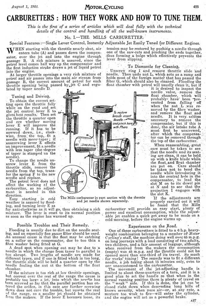
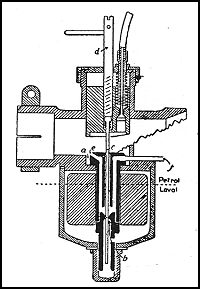
    Float chamber: Fuel enters the carburetor at (A), passing up through the strainer (B), into the float chamber (C), through the needle valve (D). The valve (D) is actuated by means of the float (E), operating through the counterweight levers (F).
    As the fuel flows into the float chamber the float rises and, acting against the levers (F) forces the needle valve down and closes same.
    As the float rises the valve closes until the float reaches a certain predetermined level at which the valve is entirely closed.
    1 From instruction books of Stewart carburetor issued by the Detroit Lubricator Co., Detroit, -Mlich. (manufacturers).
    If the float falls below this level, because of the diminishing supply of fuel in the float chamber, the valve is automatically opened and more fuel is admitted to bring the level up to correct height.
    From the above it will be seen that the float chamber constitutes a reservoir of constant supply, in which the height of fuel is always at the same level. This contributes to efficient metering.
    Dashpot chamber: From the float chamber the fuel flows through passage (G) into the dashpot chamber (H). It also passes through the holes (I) in the valve piston into the central space (J) which surrounds the tapered metering pin (W).
    The metering valve has a piston (L) at its lower end and which operates in the dashpot chamber.
    The object of the dashpot is to improve the performance of the carburetor by steadying the action of the metering valve during acceleration and low speed operation of the engine.
    Name of Parts
    A, fuel supply inlet; B, strainer; C, float chamber; D, gasoline needle valve; E, float; F, counterweight levers; G, gasoline passage; H, dashpot chamber; I, gasoline passage; J, gasoline passage; K, dash adjustment lever; L, riashpnt piston; M, metering valve head; N, metering valve stem; 0, as-pirating tube or nozzle; P, primary air passage; Q, metering valve seat; R, mixing chamber; S, fuel metering orifice; T, metering pin rack carrier; U, adjustment lever clamp screw ; V, adjustment screw; W, metering pill; X, gear housing; Y, pinion shaft; Z, low throttle stop screw; AA, strainer plug; BB, air inlet; CC, throttle valve.
    The metering valve consists of a conical shaped head (M), CC stem (N), and piston (L). This is the only moving part in the carburetor proper. It slides up and clown in its guide, formed in the body of the carburetor. The upper part of this valve contains a jet or nozzle (0) and primary air openings (P).
    When the engine is at rest, the conical head of the metering valve seats in the carburetor body at (Q). When the engine is running, however, the metering valve is always floating in some higher position, thereby forming an annular or ring-shaped air opening between_the conical head and its seat (Q).
    Fig. 1. Stewart model "25" carburetor, 1" size, with rack and pinion dash adjustment used on Dodge Bros. car. Side, or horizontal outlet.
    1261
    Action of Carburetor
    The action of the carburetor is as follows: The suction created by the down-ward stroke of the engine pistons draws air into the mixing chamber (R) through the primary air openings (P). The same suction draws a fine spray of atomized fuel from the nozzle (0) into the mixing chamber. The air thus mixing with the fuel forms a combustible gas for the engine. As soon as the engine begins to rotate, the metering valve lifts sufficiently to allow the main air supply to pass into the mixing chamber between the conical A head (M) and the seat (Q).
    Fuel is metered in an annular shaped orifice near the center of the valve at (S) passing between the valve and the tapered A A portion of the stationary metering pin (W). As the metering valve lifts into the higher positions, it gives increasingly larger fuel openings due to the lifting of the valve away from the tapered metering pin, also larger air openings due to the

    Attached Thumbnails Attached Thumbnails Click image for larger version. 

Name:	Document (273).jpg 
Views:	58 
Size:	768.8 KB 
ID:	272020   Click image for larger version. 

Name:	Document (274).jpg 
Views:	43 
Size:	692.3 KB 
ID:	272021   Click image for larger version. 

Name:	Document (275).jpg 
Views:	33 
Size:	713.8 KB 
ID:	272022   Click image for larger version. 

Name:	Document (276).jpg 
Views:	37 
Size:	697.6 KB 
ID:	272023   Click image for larger version. 

Name:	Document (276a).JPG 
Views:	951 
Size:	101.9 KB 
ID:	272025  


    Kinky is using a feather. Perverted is using the whole chicken

  11. #9371
    Join Date
    18th May 2007 - 20:23
    Bike
    RG50 and 76 Suzuki GP125 Buckets
    Location
    Auckland
    Posts
    10,516
    Quote Originally Posted by husaberg View Post
    First bit i see you ran the 30mm Carb Rob, but why so small...... why not at least a 34mm?
    Interesting info on carbs Husa.

    The 30mm Carb fitted without having to modify any part of the inlet tract, making it easy to swap back to the taper bored 24.

  12. #9372
    Join Date
    30th September 2008 - 09:31
    Bike
    Suzuki GP125 Bucket
    Location
    Auckland
    Posts
    1,969
    Quote Originally Posted by wobbly View Post
    I discovered the 135mm inlet rule of thumb on a TM125 MX engine used for 125 class kart shifter racing .

    That length is for a reed - the RV needs to be alot shorter again.
    Wobs comment on inlet tract length.

  13. #9373
    Join Date
    30th September 2008 - 09:31
    Bike
    Suzuki GP125 Bucket
    Location
    Auckland
    Posts
    1,969
    And Just for you TeeZee I waded back a hundred pages or so and collected up Wobs comments on setting up 2-Stroke carburation.

    Quote Originally Posted by wobbly View Post
    Lambda is not a reliable tool for any length of time in a 2T.
    The heated ones last a bit longer but no matter what probe type is used they get contaminated and don’t read correctly in a very short time frame.

    EGT is very simple.If you find peak power at say 1240* ,and know what the RAD was on the dyno, then its easy to construct a jetting pattern.

    Every 3% rad = 1 jet size in a Kehin or Dellorto that use metric sized jet holes.

    Always start on the rich side and jet down to the set EGT.

    Best example I can give was at Vegas World Kart Champs. In practice we went down one or two jets every run - as long as we saw a temp rise around 50* per jet,and the ground strap mark was clean at 3/4 length, then we were making more power.

    At RAD 101 we had 1260, going one more only raised egt about 20* so NFG going there.
    This was a 162 jet before we changed.

    On qualifying morning it was cool and RAD104 - up one jet to 165 and we saw 1255 - on the money, qualified 2nd by 0.003 sec.

    First race after lunch was RAD98, down 2 jets, won the first heat easily and saw 1265* and immediately were accused of cheating,for blitzing the Yank Champ down the shute..
    He hadnt jetted down enough for the hot afternoon RAD change.
    Its that simple,once you have a baseline.
    You can use the egt and the CHT as well, but thats another story.
    Quote Originally Posted by wobbly View Post
    Have tried the remote hose to the Lambda thing and although the probe lasted better it was slow responding to the extent that it is impossible to log the Lambda output against rpm/Hp on the printout.

    The reading I think was about 2000 rpm behind the engine when accelerating at 300 rpm/sec.

    Dynojet has an expensive add on kit that uses a pump to draw the gas thru a tube that goes in the muffler, this has a filter element in it so should make the probe reliable.

    But it doesnt work on a 2T - even apart from having something affecting the test by altering the outlet area of the muffler itself..
    I have seen one Dynojet session where the customer had to pay for 2 probes in a 4 hour test cycle. NFG.

    Re using EGT and CHT.
    The only probes that are worth shit come from Exhaust Gas Technologies.They guarantee them for 2 years,and I have had no problems since changing to them.

    They sell probes to Nascar/IRL/F1/MotoGP teams with a guarantee - the only guys to do this with exposed tip,high speed temp sensors.
    The company sells Digatron gauges on Ebay,and having just started to use one with 2 screens and 5 functions - im sold.

    The ones sold by Mychron etc for kart use are crap, seen several brand new setup last two laps.

    Using the two gauges together,especially if you have say a Digitron data logging gauge,makes jetting much easyer.

    Basically when the jets are rich, both egt and cht will rise then fall together,when doing a full throttle all gear run.
    You can keep dropping jets and be sure that all is well as long as they both rise together - with the one caveat I stated above.

    One Keihin main jet size should lift the egt around 50*F, if you only get 20* rise from a previous jet then what is happening is this. There is only "x" amount of energy in the fuel ingested.This can end up in the trapped, expanding gas - making power.

    It can end up in the water, via the head and cylinder wall,and depending upon the com or ignition point,alot simply exits the port and heats up the pipe.

    BUT - as soon as you go overly lean,the combustion pressure/temp gets to a point where instead of heating the combustion charge, the flame front starts creating free radicals.

    This uses a huge amount of the available energy,and instantly the egt drops.

    Once free radicals have formed,they keep the process going,causing destructive deto to get worse and worse - thus the egt drops thru the floor.

    You need exposed tip,fast probes to see this quick enough to save the engine.

    Thus on the gauge,the CHT keeps rising fast,but the EGT slows and can drop down again.

    In the above example I gave, the egt only rising 20*F pointed instantly to the fact that we were approaching deto point.

    By watching the two temps track upwards together it is real easy to get a handle on what the engine wants, to make peak power - just short of deto.
    Quote Originally Posted by wobbly View Post
    CHT is dead accurate on a watercooled head as far as the rising temp is concerned.

    The washer reads the heat load into the plug,its a bit slower than on an air cooled engine but the data is still valid.

    More important is the fast response needed for EGT tracking,so you see immediately the temp slowing and then dropping when deto sets in.

    The A/F meter is no different than the Lamda readout - the sensor soon dies due to contamination of the sensing surface.NFG.

    The last injection setup I worked on we built an interface for the ECU that converted the EGT reading to the Lambda scale that the computer recognised.
    This worked well on a Jetski setup,that is usuall all go or none.
    Quote Originally Posted by wobbly View Post
    You must take into consideration the fuel being used, and how the factory engineers approached the problem.

    Unleaded ( FIM that needs gloves and a respirator ) will go to 15:1 but must be run VERY rich to achieve best power with that level of com.

    Leaded was run up at 19:1 in GP engines and at the end of the day the result was that the advance curves changed very little.

    The big advance was in using the powerjet solenoids.

    The unleaded scenario uses BIG powerjets ( 60 + ) to turn off the rich mixture past peak power.
    The leaded setup was very lean at peak power, so only needed small ( 35 ) powerjets to keep the pipe temp up, over the top of the pipe.

    Later of course that bastard Thiel came along and did the clever thing of PWM controlling the powerjet, thus even closer continuously matching the A/F ratio to the pipe temp needed for max power.
    Quote Originally Posted by wobbly View Post
    The issue that your test doesn't address, is that with pump gas you may be able to get away with 13:1 com.

    With AvGas its just starting to work properly at 15:1 and this attribute will always far outweigh any advantage flame speed or whatever may be contributing from the pump gas scenario.

    The other issue is that unleaded fuel works best with plenty of advance, no com, and rich as hell.
    AvGas loves com, loves running lean and hates advance, so you need to spend days on the dyno just optimising for the fuel.
    Quote Originally Posted by wobbly View Post
    Using a 10 plug there is 0.2 cc in the plug hole. When drawing a chamber in CAD, with a straight line across where the threaded hole would be, you add 0.2 cc to the calculated vol. A 9 series I would say was closer to 0.3cc.
    Quote Originally Posted by wobbly View Post
    Yep Mitre 10 is the simple answer to easy access to Acetone.
    About a cup full in 5L does the job in AvGas.

    Re the powerjet sizing the answer is NO NO NO.
    Cant be bothered now but work out the AREA of a 160 main and subtract the AREA of a 0.35 powerjet.
    Quote Originally Posted by wobbly View Post
    Area 1.6 main = 2.010, less area 0.35 = 0.0962.
    Main jet should now be 1.56,closest is 1.55 with the powerjet .
    Try this without switching first to check equivalent egt to original setup.
    Quote Originally Posted by wobbly View Post
    Matters not how the best temp was derived, on track or on the dyno.
    With the gauge running and say a 180 main, then going down to 178,if I only see a small increase in temp ( 20*F) then that instantly means that more heat energy is being used somewhere - not in heating the Ex gas to make power.

    If the original temp was 1240, then that will be the ref temp for any air conditions on any day.
    With the example I gave we had a 3 jet spread during the day, a very cool dense morning, and a very hot dry afternoon.

    In both cases the egt settled at around the same mark. One jet leaner and we would be in the danger zone - one richer and we wouldn’t be the fastest by a mile as we were.

    Quote Originally Posted by wobbly View Post
    Each engine is different but if a setup has the optimum com and the timing in the ballpark of 15* at peak power, then Avgas or leaded racegas around the equivelant RON
    will always be maxed out at around 1250* - @ 150mm min from the port.

    Unleaded likes to be alot richer and makes more power with more advance so that setup makes best power at around 1050.

    Not enough com or advance, and the peak safe egt will rise, but power wont, it will just rev on more due to the higher wave speed. But you still have it wrong about the air on the day.

    You can jet to get the optimum egt, no matter what the RAD says, and it will be in the same state of tune - just using all the oxygen in the air available and mixing it with the correct amount of fuel.

    On a hot day,or low Baro, it will hit 1250 but simply make less power, due to less oxy and thus less fuel = less BTUs burned.

    The 400 F3 we thrashed on the dyno and at 12,000 held by the dyno for around 30 secs it settled at 12000* F - 96 Hp with no fade.

    Thus this is a good safe baseline for the new owner who may not have the tuning smarts to determine what is good or not - but if he has to change jets 3 times during a day to see 1200 then he will be well on the way to learning what to do.

  14. #9374
    Join Date
    4th January 2009 - 21:08
    Bike
    YLR150RR and a RD350LC
    Location
    Not far from Ruapuna
    Posts
    2,368


    500cc flat 4 2t from 1942, homebuilt by Denny Jones
    My neighbours diary says I have boundary issues

  15. #9375
    Join Date
    20th January 2010 - 14:41
    Bike
    husaberg
    Location
    The Wild Wild West
    Posts
    12,150
    Quote Originally Posted by Yow Ling View Post

    500cc flat 4 2t from 1942, homebuilt by Denny Jones
    Nice video Mike. Unfortunately the post war ban on supercharging limited it's use a bit though. So he build some 4 cylinder Diesels, like this one, afterwards.
    Attached Thumbnails Attached Thumbnails Click image for larger version. 

Name:	Document (278).JPG 
Views:	31 
Size:	406.5 KB 
ID:	272066   Click image for larger version. 

Name:	Document (277).JPG 
Views:	58 
Size:	447.3 KB 
ID:	272065  
    Last edited by husaberg; 22nd October 2012 at 16:17. Reason: gramar


    Kinky is using a feather. Perverted is using the whole chicken

Thread Information

Users Browsing this Thread

There are currently 13 users browsing this thread. (1 members and 12 guests)

  1. wobbly

Posting Permissions

  • You may not post new threads
  • You may not post replies
  • You may not post attachments
  • You may not edit your posts
  •