Page 630 of 2703 FirstFirst ... 13053058062062862963063163264068073011301630 ... LastLast
Results 9,436 to 9,450 of 40534

Thread: ESE's works engine tuner

  1. #9436
    Join Date
    31st July 2005 - 11:15
    Bike
    a shed full of crazy shit
    Location
    Palmerston North
    Posts
    2,201
    I've got a few to weigh in;
    Tz125 4jt.
    Rgv vj19 (lighter than the 22/23)
    Cbr which I can nearly get too now all the woods gone from the woodshed.

    And of course the GPR (which was lighter than the nx4)..

  2. #9437
    Join Date
    4th August 2007 - 17:55
    Bike
    NSR300 F3, ME BUCKET
    Location
    Wellington
    Posts
    2,656
    Quote Originally Posted by Bert View Post

    And of course the GPR (which was lighter than the nx4)..
    And go around corners the same if not better. Instead of playing with old Ali junk just get scott to build you 4 frames. I am sure he would do a bulk deal.

  3. #9438
    Join Date
    31st July 2005 - 11:15
    Bike
    a shed full of crazy shit
    Location
    Palmerston North
    Posts
    2,201
    Quote Originally Posted by richban View Post
    And go around corners the same if not better. Instead of playing with old Ali junk just get scott to build you 4 frames. I am sure he would do a bulk deal.
    Just think if it was capable of taking a bigger motor as well you could do all sorts of racing.
    That's right it can!!

    Just get in line; I want another one...

  4. #9439
    Join Date
    18th May 2007 - 20:23
    Bike
    RG50 and 76 Suzuki GP125 Buckets
    Location
    Auckland
    Posts
    10,516
    Page 630 ....

    A Big post about Wobs views on pipes, more can be found on page 620

    Quote Originally Posted by wobbly View Post
    Well thats one of those old wives tales ( or tuners tale if you like).
    The depression created in the case by the diffusers outgoing + wave,sucks like hell on the cylinder, via the Ex duct, around BDC.
    That is, if its properly designed for maximum effect at peak torque.
    There is simply insufficient time for this effect to suck mixture thru the transfers, empty the case, and then start sucking the reeds open.
    It just doesnt happen.Its lies, a myth,not reality at all.
    And to make it worse, if the diffuser is designed correctly, when it works best, there is the least time period ie full noise.
    In a race engine at peak torque (same as peak power in many cases)the reeds do not start to crack open until the piston is travelling upward and is covering around 1/2 the transfer height.
    So in this respect this is about the only similarity a race engine has with your dads old lawnmower,in that the rising piston creates some of the depression needed to initiate intake suction.
    As I have posted before,this can be "tuned" in as much as correctly timing the wave return at the reeds as + just as the case starts to go -, you create the max effect possible by using free energy to open the reeds.
    Sure, the better the pipe, the sooner the case goes below a zero pressure ratio, and this has only a minor effect on the reed opening point - but there is NO FLOW created by the pipe "sucking" on the reeds, its bullshit.
    Rotary valve intake tuning is highly affected by resonance effects due to the very "sharp" open/close scenario,creating high amplitude "shock" and standing waves in the carb - but inherently the pipe is working with the cylinder contents, not the case vol, and thus the design parameters are to all intents identical.


    Look again at the F3 engine I am building - the reed tip lift is only just starting to allow real flow, when the transfers are closed.
    When in full resonance mode ( in this case its designed to work best in the overev ) the reeds open a little earlyer, and stay open alot longer due to intake "ram" but there is little evidence of pipe effects, even the reed closing side of the trace has nothing to do with "pipe suction"..
    Quote Originally Posted by wobbly View Post
    Only the middle reed opened - wow, a real odd artifact you would never expect,but that sort of shit happens all the time.
    I would get a migraine trying to fathom that one.

    One other point to mention here, one I have posted before somewhere.
    If you look at the delivery ratio of a race engine, then calculate how much actual mixture is transmitted thru the transfers into the cylinder - compare that to the swept vol of the transfers, you realize that in most engines,what is sitting in the ducts is more than the vol going to the cylinder.
    So where is all this so called case flow that supposedly opens the reeds, it aint there at all.
    This is why new technology has the transfer ducts getting smaller and smaller,the stored volume has less inertia and gets into the cylinder quicker with the same pressure ratio across the ports.
    Quote Originally Posted by kel View Post
    TZ mentioned how the Honda RS pipe inlet is larger than the GP exhaust port outlet, while this is common place on 4 strokes for the purpose of AR I wasnt aware it was used on 2 strokes but on reviewing RSA photos I came across this
    Attachment 239992
    Attachment 239993
    Jan Thiel "One wants the pressure wave coming back into the cilinder but NOT the burned gases that are hot and can cause detonation!"
    Makes sense.
    Quote Originally Posted by wobbly View Post
    Mild steel pipes will always rust and or go black,the only way to help keep them looking OK is to use Castrol R.
    You have to rub it on with a rag every time the bike is run, and eventually it will burn in like a wok surface preventing rust, but you cant stop the header going black.

    All the common big end sizes are available in the newer flat cage design, as this type is used in all current road and race engines.
    And who is going to say to you that your engine is illegal coz its got a modern cage design.

    And re the step in a Honda exhaust duct.
    When using a T port or a properly designed tripple port exhaust, the area just outside the port is way too big during the blowdown phase,and alot of velocity is lost.
    I have found that a good rule of thumb is to gradually reduce the duct exit at the flange, to around 75% of the total chordal area.
    This will often equal the area of just the main port in a tripple setup.
    If you make the duct exit the width of the header, and then reduce the height, forming an oval to give the correct area, a heap of power is created, in part due to the much better flow from the outer parts of the port width of a T or the
    aux ports in a tripple..
    Steps work OK, but a CNC formed oval to round transition in the flange works best.
    Note well, this technique DOES NOT work in a single Ex port engine, no matter how big it is.
    Quote Originally Posted by wobbly View Post
    The only connection between Rotax and Aprilia was that the race team used the 250 V twin cases from Rotax at the beginning of their attack on that class.
    Very quickly they made their own cylinders, and later their own cases as well.
    Then they got sick of the crap gearboxes and did their own, as the original design by Bombardier was for a 125, and this got used even on the 250cc single, with predictable results there as well.
    The early Rotax had 20mm pins that were too small, and the later design had 22mm - when Hondas bulletproof cranks were 24 and 25mm.
    So yes the uprated design you mentioned probably had some actual QC done on the parts, unlike the Rotax shit - they should have been shot very early on and prevented millions of dollars and grief being spent on broken engines for no good reason.

    The nozzle is part of the Exhaust duct, you can weld the duct or counterbore it and press in a sleeve to be ground out to the right shape.
    Honda use a cast oval to round transition male spigot flange in the A kit 125 engines, as well as some years of the 250 V twin design.
    And yes the RS125 header size is way big for a 100 - but having the correct size oval shape in the duct would reduce its volume and increase velocity and power a heap.
    The design I have just done for the RGV100 has an oval duct nozzle the area of a 31mm circle,that transitions out to a 36 diameter round header bore in the flange.
    This matches an Ex port area capable of achieving an easy mid 30Hp number.
    Quote Originally Posted by wobbly View Post
    Removing the step from a Honda means you remove the oval nozzle restriction before the header, that increases duct velocity.
    Bigger is certainly not better.
    As an example when I did testing for the new Luyten 125 cylinders, I counterbored the duct and made inserts to change the oval size.
    It started with 41 by 37, I dropped it to 41 by 35 then 41 by 32.The change was worth around 2Hp everywhere, but especially in overev.
    Then I added a hand ground 41 by 32 oval, to 41 round, transition in the spigot - and picked up another 1.5 Hp, putting that cylinder over 50 RWHP for the first time.

    The Rotax Tandem twin was the first 250 class engine, but it was way too long to get good chassis geometry, they then did the V twin for Aprilia, carrying on making the tandem for karting.

    A747 is a synthetic hybrid with caster added, it doesnt work on pipes ( just as well at the price).Probably still the best 2T oil you can use.
    Quote Originally Posted by wobbly View Post
    Another good source for big ends is Thompson - I use these in KT100 crank rebuilds as the needles are already graded.
    The rear cone nozzle in the old Honda manual is well out of date.
    A later version was developed by Helmut Fath and was first used on Fast Freddys 250 where one stinger was 150 long the other was 450 long.
    This better design has a short 10mm "nozzle" of the correct size to create the pressure restriction, then a short taper, up to a stinger tube approx 2mm bigger in diameter.
    The bigger stinger and the reverse taper basically remove this resonant tube from the equation, and the stinger length becomes irrelevant.
    Under normal conditions the wave action bouncing up and down the stinger ,off the open end to atmosphere, creates varying bad effects on the reverse cone waves.
    The pic shows a section of one for F3 - 400.
    Rear cone welds onto LH side, stinger pushes into RH side and welded as well.
    Another side effect is that there is no welding ( dags) to affect the flow where the rear cone is attached to the tube.

    Dont know about Loris and his anal action, but I was with Benson and the team at Cowes one year having diner on the corner, where Max had a new "girlfriend" that night.The next night the same "person" was on his lap,as a man.
    Tell his new wife that one, and see if the bulge in the back of his pants is stronger than the one in front.
    Quote Originally Posted by wobbly View Post
    In the testing I have done, the volume of the resonator chamber isnt critical, once you have reached a certain size.The best place to start is equal to the cylinder displacement, and this will "work" every time.
    Fitted to a world champ ski engine, these chambers, operated by a flat, throttle slide plate,added over 30% more power at 1/2 peak rpm.
    They seem to work very similar to a PV, in that the pipe effects are dramatically reduced in the area where the wave action is way out of phase with the port.
    This is seen in the sim, and on the dyno, in that you can change the pipe dramatically, and it has little effect when the PV is down, or the chamber is open.
    Quote Originally Posted by wobbly View Post
    If you wana talk pipes, take a gander here.
    Prototype set for my 100Hp+ F3 - 400 RZ in Aprilia 250.
    Though personally I like the radial Brembos with adapters better.

    Having sharp corners, even up at the center section kills power big time - better to have 3 small cuts than one sharp one.
    Quote Originally Posted by wobbly View Post
    Been there tested that on Ti pipes, if you have ever tried to hammer Ti or Stainless you will know its all but impossible.
    As long as the angle changes are small like the sections in the pipes shown, with fusion only welds,then hammering the joins makes no difference to power.
    Nigel is anal about the hammering and does a real good job just to be better at it than me,but as the testing showed its not needed with quality fusion welds,it makes my customer pipes just a bit more affordable.
    If I hammered every weld of a single pipe, it would take 3 days instead of 2.
    But even he wanted to have sex with the first set I made for the RS500.
    The venturi is 27mm the stinger ID is 28.6
    Quote Originally Posted by wobbly View Post
    Yep, 304 Stainless, a real bitch to roll and work with, but easy to weld.
    I hate doing them in SS, and now get Tyga to do the production pipes off my patterns, as 90% of the work is in getting the shape and cuts correct.
    Another small point about weld hammering is that if its done "too well" then you get the same issue as found with blown pipes.
    The angle changes become smeared and you loose power.
    Especially at the interface of the header end, and the rear cone to the mid, these have to be a "sharp" angle change, different issue to a too sharp angle cut, that isnt a change in pipe section.
    Quote Originally Posted by diesel pig View Post
    Interesting, This probably accounts for the works pipe I Have see on the interweird with blown headers and the rest welded.
    Quote Originally Posted by husaberg View Post
    What about Fleck , Hiroshi Naito (1971) and Robinson in regards to STA

    http://www.suzuki-rg500.com/water.htm

    WATER INJECTION
    By Randy Norian
    SAE paper 931506, expanding the torque curve of a Two Stroke Motorcycle race engine by exhaust water injection", by Robert Fleck at QUB. In this paper, they built a simple system to inject water into the headpipe of a 125cc test motor and recorded power gains of up to 24% in the lower midrange. I decided to copy their setup and was able to reproduce their results on the dyno. After that, I decided to built a usable system that would function smoothly on my streetlracebike.
    But first, some numbers.
    Fleck recorded pipe temps at several points along the exhaust pipe. In the diffuser, without water injection, he recorded gas temps rising from 425 deg Cat 9000rpm, to 510 deg Cat 10800 rpm.
    With the water injection active, the same sensor recorded temps of 150 degrees Cat 9K RPM, rising to 420 deg Cat 10800 rpm.
    Lets go back to the equation for tuned length.
    If we consider a stock RG500, this distance is about 84cm, (33 inches) and Eo is 188 degrees. Using Vs of 1700 fps, this formula predicts a peak power RPM of 9684 RPM. This is a pretty good estimate, as my bike peaked at 9500 rpm in stock form.
    Now we consider Vs with water injection active, let’s say we have a mean 200 degreee C drop in gas temps. If we use Vs of 1700 fps with no water, this figures to a new Vs of about 1430 fps with water. Plug that into the equation for tuned length, and our same exhaust pipe is now tuned for a peak of 8150RPM. So we have been able to shift our peak power down almost 1500 rpm, by injecting water. Obviously, this will reduce the peak rpms of our motor, so the trick here is to turn off the water at some point and let the engine rev out normally on top.
    If we were able to cool the pipes all the way down to room temperature, the stock Gamma would have a peaking RPM of just 6270 RPM. Clearly, pipe temperature has a huge role in determining the rev range of a pipe/port combination.
    Controlling pipe temperature is an effective way to alter the tune of a 2 stroke

    I note Aprilia used use carbon sleeves to raise the temp of the pipe for top end
    Quote Originally Posted by wobbly View Post
    I was in the pit at Philip Island when Doohan tested the NSR with the water solenoids on the headers.
    He did 3 laps, immediately full noise as he always did.
    Came in and said it was a piece of shit till 1/2 way down the straight, but had heaps of power off the bottom and lost around 1000 rpm on top.
    They plugged in the laptops, and I assume wound back the squirt volume.
    Another 3 laps, and he said it now came on song much earlyer, but had lost most of the bottom end, and was still 800 rpm down on top speed..
    More festering on the laptop, back out again.
    This time no useable gain in bottom end,slow to come on the pipe, and still no overev power.
    Mick just said - "maaaete,turn the fuckin things off and give it a go."
    Went out and put it on pole,easily.
    Talking to Burgess in the Cowes pub that night he said it seemed that to get enough water into the pipe to do some good for the bottom end, it took too long for the temp to rise back to "normal" again, so they had ripped the whole thing off, and binned the idea.
    Adjusting the PV curve gave better, repeatable results.
    Quote Originally Posted by wobbly View Post
    I was just pointing out that the idea of using water, great as it may be in theory, and on a dyno when looking for bottom end, it "works" just fine.
    But in a controlled test to see if its was usefull, it failed, as the systems effect had to be reduced so much that any gain in bottom end was still offset by a loss in the top end.
    As Burgess said,when the effect was usefull,it took too long to reheat the pipes.
    My thoughts,from the testing I did with a PV and ATAC operated separately ( instead of combined together as many MX engines have now) is that this works real well with no down sides at all,and is easy to implement.

    If you or someone can refine the original idea - then great.
    Quote Originally Posted by wobbly View Post
    Im not allowed Chokky Fish bugger it as I have type 2,that is under control with diet and single malt.
    But the powerjet switched with a solenoid is done just after peak power,as the engine is most efficient at peak torque,where it needs the most fuel.
    But the carb doesnt know about efficiency, only bulk flow past the main jet - and the flow keeps rising as do the revs,so the mixture goes rich over the pipe ( thus reducing the temp).
    By switching off some of the orifice area ( PWM is way better) we can lean down the fuel curve into the overev and heat the pipe up way more than is possible at peak torque.
    On a HRC - RS250 for example the solenoids are activated at 12200 to 12800 ( adjustable plugs in the loom) and it will rev hard to 14000.
    Without the powerjets it falls dead just past peak power at 12000.
    Quote Originally Posted by wobbly View Post
    To get around 38 crank Hp from an RGV100 ( to create mid 30RWHp) the T port needs to be up at 198 duration.
    This is governed entirely by the blowdown available when the transfers are in the right place as well.
    Having the T port as well as the aux ports may allow the exhaust port to be dropped a few degrees in duration,this then increases the range where the pipe is in resonance,giving a wider spread and no drop in peak power.
    I need to measure one up though to see what is possible when it is sleeved back from the 56 bore to 50mm

    Edit, its 54 bore,so has a stroke of 54.5 unlike the earlyer engines.
    Quote Originally Posted by wobbly View Post
    "MSV is high at 25M/Sec", forget all that old shit - here is the go with squish.
    In any race engine the squish height should be set at the minimum achievable,just shy of the piston tapping the head when overeved.
    In a bucket where the norm is "only" 13000 there is no reason to have any more than 0.6mm.
    The squish width based on MSV is a theoretical number of little relevance when we are running the piston in the powerband just short of hitting the head.
    But with a parrallel squish ( ie curved same as piston dome rad - or a straight cut with minimal divergence) then in most cases we can use 40 to 45% squish area.
    This generates MSV numbers in the high 30 M/Sec region.It has been stated in a few references that " high"squish velocity will bump up mid power and reduce the top end.
    Yes, in a limited view of things it does.But now that we have digital programmable ignitions thats rubbish.
    The high MSV increases turbulence in the end gases, this increases flame speed, and has the same effect as high com or too much advance.
    Simply retard the timing and the rpm comes back, but you keep the power generated by better turbulence burning up more of the end gas trapped in the squish.

    One point to remember is that the best radius on the squish corner into the bowl is no radius at all.A sharp corner with just with a rub of sandpaper to get rid of the ragged knife edge, works best.
    And with any of the race type plugs we are using approx 1mm of unthreaded plug end should be protruding into the chamber.
    The old B10EGV was originally designed to be used this way by NGK, but nowdays the trick plug is a R7376-10, this plug makes more power than any other tested with around +2 Hp better than an expensive Denso equivalent, here is the test i have shown before.

    Here is a pic of one of several "form tools" I have used for years cutting chambers.
    Now there are plenty around I always use CNC to generate a toroid insert, based on a CAD construction of the chamber, as its simply too hard to get a good shape ( and is a prick to measure properly) when doing it by hand.
    Page 305

    Quote Originally Posted by wobbly View Post
    Whats inside your head then.
    KTM250 open kart engine for reference.
    CNC toroidal,0.8mm squish,38M/Sec MSV 13.5:1 on pumpgas.
    Quote Originally Posted by wobbly View Post
    The Starmaker shape was stolen from diesel tech, but as it shrouded the squish from the main body of mixture in the chamber, it was doomed from the onset.
    The material is aluminium bronze, I would use beryllium bronze if cost wasnt an issue, the stock head itself I machined away to suit the insert.
    In this case we attack all the relevant issues involved, with small detail tricks.
    The squish band has a very highly heat conductive bronze surface that runs cool and keeps the end gases from overheating and thus forming radicals that lead to thermal runaway - deto.
    Bronze inserted "rings" only do 1/2 the job as they have a heat joint barrier no matter how well fitted they are.
    The one piece insert is far stronger than plain aluminium in such a big bore, thus the water can be run much closer to the places its needed, in the squish area , and around the plug threads, reducing thermal hysteresis.
    And lastly, the chamber only is coated with a clear ceramic heat reflective, that retains the high temp in the chamber as the combustion gases are expanding.
    Creating more gas expansion is the holy grail to pushing the piston down harder , with less wasted heat into the water - on the other side of the insert.
    Same with the piston - only the chamber area is coated, if you coat the whole piston, the heat reflective surface becomes hotter than the raw piston underneath, again this will create deto in he squish band area.

    Offset chamber heads were patented by a dirty Doctor from EMC who sold the idea to Yamaha, that used it for one year on a TZ and in some industrial shitters, then dropped it.
    It didnt work then, and wont work now.
    As it means in effect that the once beautifully symetrical chamber of a 2T has a MSV of 60M/Sec on one side and virtually zero on the other,the end gases have no chance of getting out, overheat ,and cause deto real fast - bugger.
    And if you move the plug over as well you have just created a bigger bore in one direction, again - dumb idea.
    Never seen a fast 250G with a stock head - ever.
    Quote Originally Posted by wobbly View Post
    My take on the copper in the head would be to have it extend only to the edge of the bowl.
    Then have the alloy bowl ceramic sprayed.
    This pulls heat out of the squish, but keeps the heat in the combustion area to do some work.
    Only issue is the same as bronze inserts, there is still a joint face that will dramatically slow thermal conduction between the copper and the alloy.
    Quote Originally Posted by bucketracer View Post
    .

    The 1987 Honda RS250R had the ATAC system ........... its got to be worth a try in a Bucket
    Quote Originally Posted by wobbly View Post
    Fast Freddies 500 tripple had them on 2 cylinders as well, but I found that the combo of independent atac and PV was the shit.
    Adding them to a non PV cylinder is an easy way to gain a heap of free bottom though.
    The clear ceramic coating I have NOT being using for years on KT100 pistons and chambers where its illegal, nor in World Champ winning stock class jet skis at Lake Havasu.
    Several tech inspecting teams have commented about how lean the middle of our pistons run in comparison to the squish band,I told them that was all in the jetting of course.
    Quote Originally Posted by wobbly View Post
    The material depends upon the application.
    Bronze is quite "strong" and can be used to create a complete insert, or just bands pressed in.
    Copper is softer than poo so wont hold its shape, but has better thermal conduction.
    I believe the best setup would be a combination, but always keep in mind about boundary joints forming a big barrier to heat transmission.
    Quote Originally Posted by Fooman View Post
    Generally, the more pure the alloy, the better the thermal conductivity. As noted, the more pure the alloy, the weaker it is.

    Bog std copper (unalloyed) has a thermal conductivity of ~380 W/m/K
    8% Aluminium bronze - 70 W/m/K
    5% Tin Phospher bronze - 80 W/m/K
    Al/Ni/Fe bronze - 38 W/m/K
    357 Al casting alloy (bit of a guess at a typical cast alloy) - 152 W/m/K
    1100 (99% pure Al) billet (strong as mashed spud) - 221 W/m/K

    If you want to improve the heat transfer over the boundary, use an insert with a greater thermal expansion than the body of the head - the additional pressure at the interface improves thermal conductivity. There may be an issue with thermal cracking in the head however...


    FM
    Quote Originally Posted by wobbly View Post
    Three Bond 1104 Liquid Gasket Grey is available from Northern Accessories, the very best and is copied as Yamabond etc.
    You must remember that ANY RTV based goop is NOT fuel resistant, so will not seal anything properly that is exposed to petrol long term.
    The red hi temp RTV works well on exhaust spigots etc, even works to kill noise, when beads of it are run along a chamber.
    Quote Originally Posted by wobbly View Post
    I did a heap of testing for karts to try and get the noise below the newly set Db limits.
    The best muffler core material is a trade off between open area - greater open area enables the packing to absorb more "noise",and the issue of the packing being blown out thru the holes.
    In the end I settled on commercially available perforated 1mm sheet steel that is easy to roll up and tack weld along the joint.
    Anything with approx 2mm holes on 3mm centers is the go.
    The only packing that works properly and wont get blown out easily is called SilentSport muffler packing.Its easily the best and can be bought from MotoWorks in ChCh.
    The other issue tested is power.Anything but a densely packed muffler will loose power,and making the core ID the same as the OD of the stinger seemed to be the best setup as well.
    Quote Originally Posted by wobbly View Post
    The ring pinned on center setup is the best way to do it.
    As the ring drops into the Ex port at its widest point, then is pushed back in by the corner rads,having the gap dead opposite the Ex means the ring moves symetrically in the groove.
    The ring ends contact the pin at the same time,thus preventing any issues with one end banging on the pin continually from one side.
    As long as the boost has a nice chamfer on its top edge all is fine with the ring ends.
    Quote Originally Posted by wobbly View Post
    With todays technology the bar can now be raised to around 40 crank Hp without too much drama involved, and thus achieving around 35 RWHp.
    Its just a matter of careful parts selection and very careful assembly.

    The alloy inserts for the TZ350 was the customers choice - once its all proven, and we get a handle on what the engine likes, then I will do some bronze ones.

    AvGas in NZ is all LL100, this is low lead 100 octain.But the rating is defined differently in avaition.Its approx equiv to 100 "pump" gas, but has a lean rating of 100 and a rich rating of 130.
    MNZ Appendix E defines avgas as max 112 MON amd max 108 RON.

    Avgas, or any leaded "race" fuel reacts completely differently to unleaded pump gas.
    In general terms the unleaded hates compression, but loves timing.Avgas is the opposite in that it makes more power up to the knock limit with more com.
    Unleaded makes better power when run rich,avgas makes more the leaner you go.
    Tuning in the old days with RS and TZ engines meant using lean mains and small powerjets ( 35 ) as turning off a big jet over the top would mean being too lean in the overev.
    Nowdays the unleaded fuel runs rich at peak power, then uses a big powerjet ( 55) to create some heat in the pipe over the top.
    Quote Originally Posted by wobbly View Post
    Race gas bought in drums really is" low lead race gas", nothing wrong with it - but hard to get the same stuff in many places.
    The stuff in tanks at stations/tracks is "old" avgas.The best, and only way to be sure of what you are getting is to go to any local airport and buy Avgas - it is tested regularly and is guaranteed to be fresh and to spec - has to be, or the Lycomings would all fall out of the air - bad.
    Quote Originally Posted by wobbly View Post
    Having multi cone sections gives the designer the ability to shape the power curve to the desired application.
    Add to this 2 stage headers and you can achieve any wave amplitude correction needed with a 3 stage diffuser.
    Here is a design I did for a Euro champ winning 50cc Malossi,it has a nozzle in the exhaust duct with an oval to round transition in the flange.
    A two stage header, 3 stage diffuser with the steepest angle in the middle.
    A killer pipe for the cylinder porting as it was used for long track racing only.
    Graph is crank Hp
    Quotes about pipes from pages 282 to 330 posted here on page 630, more to come on page 640

  5. #9440
    Join Date
    18th May 2007 - 20:23
    Bike
    RG50 and 76 Suzuki GP125 Buckets
    Location
    Auckland
    Posts
    10,516
    Quote Originally Posted by Buckets4Me View Post
    can you re weigh the 3ln without the side stand ...
    Good spotting .... but because the 3LN did not have a back axial and chain adjusters like the other frames did. I left the side stand on in the hope its weight would approximate the missing parts.

  6. #9441
    Join Date
    18th May 2007 - 20:23
    Bike
    RG50 and 76 Suzuki GP125 Buckets
    Location
    Auckland
    Posts
    10,516
    Quote Originally Posted by Bert View Post
    I've got a few to weigh in; Tz125 4jt. Rgv vj19 (lighter than the 22/23) Cbr which I can nearly get too now all the woods gone from the woodshed. And of course the GPR (which was lighter than the nx4)..
    It will be interesting to see the results, then we can add them to the list.

  7. #9442
    Join Date
    18th May 2007 - 20:23
    Bike
    RG50 and 76 Suzuki GP125 Buckets
    Location
    Auckland
    Posts
    10,516
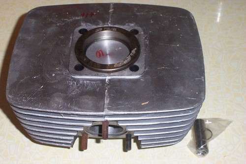
    OK, posted because someone asked about what "O" ring we used for a head gasket.

    Quote Originally Posted by TZ350 View Post
    The split ring held the cylinder central and the pull back held it secure and square in the chuck. The pull backs foot is across the main transfer ports and the threaded rod goes right through the lathes head stock and is pulled up with a nut and spacer at the back.
    The post links to some pictures of how I setup to skimm and "O" ringed the cylinder.

    "O" rings are measured on their inside diameter, ID and thickness.

    We have used a mixture of 70mm and 73mm Imperial 1/16th (1.78mm) and 72 Metric 2mm Viton "O" rings

    The "O" ring groove was cut 1.5mm deep by 2mm wide for the Imperial "O" ring and 1.75 by 2.5mm for the metric, if we messed up the imperial cut we could go deeper and wider to suit the metric size.

    The 70mm grove fits snug around the iron liner and the 72-73mm grove leaves some alloy between the liner and groove as seen in the picture.

    Head clearance volume for 7.2:1 corrected comp ratio. 10cc for Ex Closes 83 deg ATDC, 9.5cc for 80 and 9.25cc for 78.5 ATDC.

    Using a flat top piston made it easier to machine the head. I have not bothered re cutting the squish, but re cutting with a deg or two taper could be worth while.
    Attached Thumbnails Attached Thumbnails Click image for larger version. 

Name:	Head O ring. 011.jpg 
Views:	67 
Size:	61.0 KB 
ID:	272551   Click image for larger version. 

Name:	Head O ring. 005.jpg 
Views:	111 
Size:	61.8 KB 
ID:	272552   Click image for larger version. 

Name:	Head O ring. 006.jpg 
Views:	57 
Size:	62.0 KB 
ID:	272553  

  8. #9443
    Join Date
    25th March 2004 - 17:22
    Bike
    RZ496/Street 765RS/GasGas/ etc etc
    Location
    Wellington. . ok the hutt
    Posts
    21,191
    Blog Entries
    2
    Just as it is a sore point, there are engineering tables for the appropriate sizes of grooves. many people (comapnies?) seem to ignore these.

    O-rings are not supposed to be compressed or squashed in the groove, they are supposed to be 'displaced' & the groove allow the space for it to deform. Which is, as appears TZ's grooves do allow.


    My CPI barrels for example follows the classic mistake of being too narrow. May help retain the o-ring for assembly, but squashes it too much so most times they come off they need replacing. My GasGas is the same. My 50 however has the same o-ring from 2004 & 1 or 2 rings a year.
    Don't you look at my accountant.
    He's the only one I've got.

  9. #9444
    Join Date
    24th July 2006 - 11:53
    Bike
    KTM 1290 SAR
    Location
    Wgtn
    Posts
    5,541
    Quote Originally Posted by F5 Dave View Post
    O-rings are not supposed to be compressed or squashed in the groove, they are supposed to be 'displaced' & the groove allow the space for it to deform.
    Depends. Lots of variables, is static or dynamic seal, what material, temp, pressure differential.

    It's not hard, though: http://oringcalculator.eriksgroup.com/

    Note that as you get up in pressures you should be making with a slight radius across the root of the groove, and surface finish becomes critical.
    Go soothingly on the grease mud, as there lurks the skid demon

  10. #9445
    Join Date
    16th December 2011 - 14:14
    Bike
    Benelli 250 2C
    Location
    Auckland
    Posts
    139
    Blog Entries
    1
    A VERY BIG word of warning guys.

    Viton "O" rings become VERY/EXTREMELY toxic if they get burnt as in if they get overheated in service. The resulting mess will burn into your skin, and keep on attacking the skin/flesh/ bone ( in that order ) even if flushed with copious amounts of water.

    So be very careful and use a spike or latex gloves to remove the "O" ring if there are any doubts to its condition. They are very cheap so replace rather than reuse.

    I use a smear of high temp silicone between the combustion chamber or cylinder bore edge to further protect the "O" ring from any possible direct flame

    What ever you do DO NOT rub your eyes until you have washed your hands like a surgeon before he operates !!

  11. #9446
    Join Date
    8th February 2007 - 20:42
    Bike
    TZ400
    Location
    tAURANGA
    Posts
    4,087
    I complained about the Oring grooves being "wrong " in CPI cylinders, and was told I had it wrong.
    Even pointing out that every major manufacturer in the world had it right had no positive effect, so I also resorted to using imperial O rings in the "wrong" metric grooves.
    Ive got a thing thats unique and new.To prove it I'll have the last laugh on you.Cause instead of one head I got two.And you know two heads are better than one.

  12. #9447
    Join Date
    24th July 2006 - 11:53
    Bike
    KTM 1290 SAR
    Location
    Wgtn
    Posts
    5,541
    Quote Originally Posted by wobbly View Post
    I complained about the Oring grooves being "wrong " in CPI cylinders, and was told I had it wrong.
    Even pointing out that every major manufacturer in the world had it right had no positive effect, so I also resorted to using imperial O rings in the "wrong" metric grooves.
    Did you notice that imperial Orings are about 5 times the price? What is it with that?
    Go soothingly on the grease mud, as there lurks the skid demon

  13. #9448
    Join Date
    25th March 2004 - 17:22
    Bike
    RZ496/Street 765RS/GasGas/ etc etc
    Location
    Wellington. . ok the hutt
    Posts
    21,191
    Blog Entries
    2
    Quote Originally Posted by twotempi View Post
    A VERY BIG word of warning guys.

    Viton "O" rings become VERY/EXTREMELY toxic if they get burnt as in if they get overheated in service. The resulting mess will burn into your skin, and keep on attacking the skin/flesh/ bone ( in that order ) even if flushed with copious amounts of water.

    So be very careful and use a spike or latex gloves to remove the "O" ring if there are any doubts to its condition. They are very cheap so replace rather than reuse.

    I use a smear of high temp silicone between the combustion chamber or cylinder bore edge to further protect the "O" ring from any possible direct flame

    What ever you do DO NOT rub your eyes until you have washed your hands like a surgeon before he operates !!
    OK that's scary, so don't use them in exh joints for sure. Ideally this situation should not occur unless you have a head warp or machined the groove too close to the bore, but I'll take heed of your warning.
    Don't you look at my accountant.
    He's the only one I've got.

  14. #9449
    Join Date
    25th March 2004 - 17:22
    Bike
    RZ496/Street 765RS/GasGas/ etc etc
    Location
    Wellington. . ok the hutt
    Posts
    21,191
    Blog Entries
    2
    Quote Originally Posted by wobbly View Post
    I complained about the Oring grooves being "wrong " in CPI cylinders, and was told I had it wrong.
    Even pointing out that every major manufacturer in the world had it right had no positive effect, so I also resorted to using imperial O rings in the "wrong" metric grooves.
    Well to be fair you are wrong; its every manufacturer except CPI AND GasGas.


    . . . & probably a few others, but certainly the Japs always get it right.

    I used to work for a company that had a designer that always got it wrong, so it always stuck in my mind. We now have products that can take 30M immersion with plain nitrile rings but yes you do need to watch surfaces.

    and thanks for the suggestion of the imperial size, its close enough without the option of remachining it seems, not that mines got many miles on it since I put those in.
    Any thoughts on compression vs water temp? I'm about to pull the head off this week & try your insert modification.
    Don't you look at my accountant.
    He's the only one I've got.

  15. #9450
    Join Date
    20th January 2010 - 14:41
    Bike
    husaberg
    Location
    The Wild Wild West
    Posts
    12,147
    OK i are now confused. I always thought the rubber o-rings were more for water sealing yet rob has one.
    I remember the first time it was mentioned with the Air cooled two stroke singles and i always assumed it was referring to the stainless wire 4 stroke style or that or a fire ring.

    wouldn't a simple spigot serve Rob better esp as he already has a defacto copper head gasket. (Possably missing something simple here)

    I remember these Minarelli and i guess some of the other ones will do too. esp the Europeans.
    Apologies for using a web picture as i can't be arsed driving 20 km and taking the head of the Indian ME125 at my dads place.
    The pics i have unfortunately doesn't show the underside of the cylinder head (edit does now)where the small gasket fits.(only this is the aluminum one from a fifty)
    But it does give an indication to how big the finning was on a Italian 1970's two stroke 125 with a 55mm bore.

    As a whole the engine looks like this as a whole bike (the Indian ME125) is spectacularly ugly in a seventies angular kind of way.pic on right is what it should look like


    OK virtual chockyfish question. Name this flying web crankshaft (it may be a tricky one)
    It caught me out. Could be posible to make an interesting engine out of it too with a few mods. ESP as they made quite a few of them over the decades it was in production
    Attached Thumbnails Attached Thumbnails Click image for larger version. 

Name:	ring gasket.JPG 
Views:	849 
Size:	277.0 KB 
ID:	272640   Click image for larger version. 

Name:	whats this from.JPG 
Views:	49 
Size:	118.9 KB 
ID:	272581   Click image for larger version. 

Name:	Document (279).jpg 
Views:	42 
Size:	773.7 KB 
ID:	272584   Click image for larger version. 

Name:	Document (280).JPG 
Views:	35 
Size:	653.7 KB 
ID:	272585   Click image for larger version. 

Name:	Document (281).JPG 
Views:	43 
Size:	567.5 KB 
ID:	272586   Click image for larger version. 

Name:	me125 cylinder head.JPG 
Views:	30 
Size:	282.1 KB 
ID:	272592  
    Last edited by husaberg; 3rd November 2012 at 18:17. Reason: oh i get it nothing to aneal just lift and refit is that it?


    Kinky is using a feather. Perverted is using the whole chicken

Thread Information

Users Browsing this Thread

There are currently 10 users browsing this thread. (1 members and 9 guests)

  1. jonny quest

Posting Permissions

  • You may not post new threads
  • You may not post replies
  • You may not post attachments
  • You may not edit your posts
  •