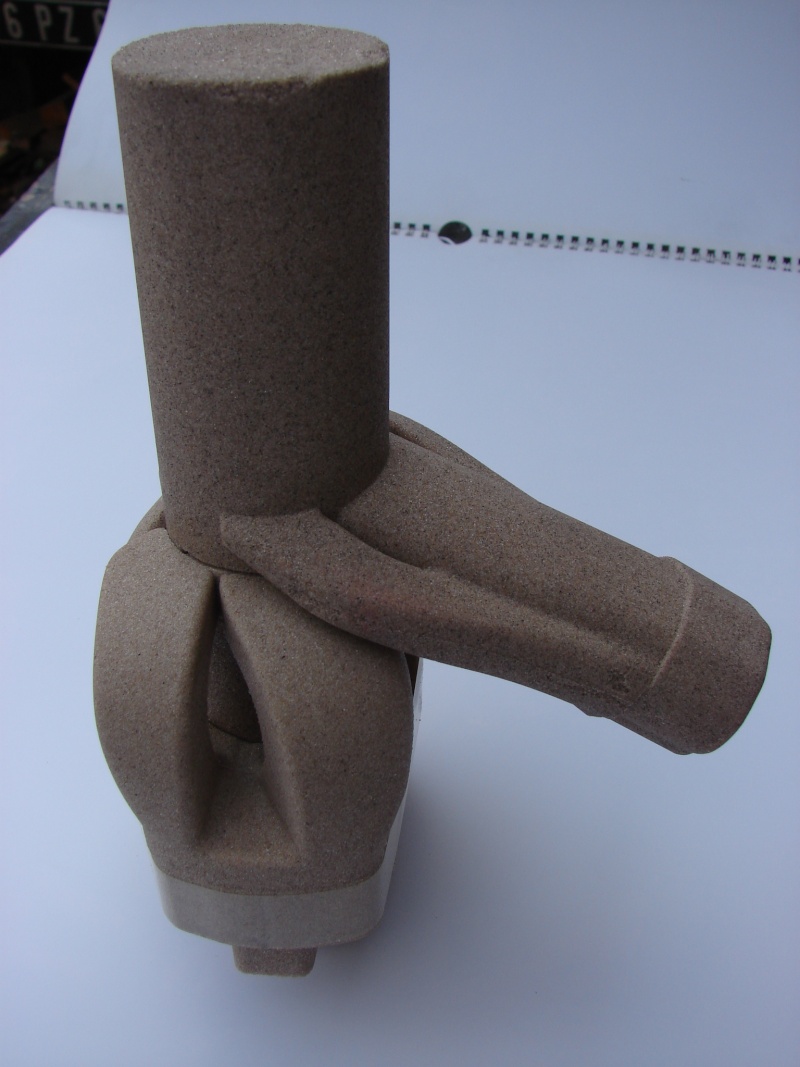
Wob, the RSA duct exit must be 39.2mm in equiv. diameter, from Frits' aprilia 102 pipe schematic

From another cad drawing posted in pit-lane by Francis Payart -which I cannot find by any means at the moment-damn research - the exit is ~33x46mm tallXwide, auxiliary ½ moons included.
I cannot find a way that will make the main+aux ports around 1600mm², in order to have a duct exit of ~75% of that. The total of the ex ports would have to be around 45mm of equiv. diameter! Seems huge

Actually, when modeling the older apc ports, it would seem it is more like 40.5 ports - 39.2 duct; or ~95%. That % would be even bigger for the bottom-risen/narrowed apf port.
Could it be that the nozzle effect is only duct-volume related and not duct-exit% related?
Or perhaps the auxiliary ½ moons are excluded from that area%.. -which you have confirmed in the past it's not the case, I think.
p.s. I don't mean to insult you Wob; you have my respect. I am just discussing my thoughts, eh..
 edit:
edit: Here it is.. Just had to go through fpayart posts et voilà:


Originally Posted by wobbly


 Reply With Quote

 Hey Wob something interesting I realised while watching a Aston Martin Mega factory doco on youtube, designers were talking about the "golden ratio' which has been used since they built the Parthenon. The ratio of 'anything' should be 1.612:1 just under 1/3 to 2/3rds, designers say everything conforming to that has natural beauty and looks 'right'. Your header to t/l , diffuser to t/l and what to do with the remainder seems to conform with that 'golden ratio'.


 .
.


Bookmarks