Page 730 of 2702 FirstFirst ... 23063068072072872973073173274078083012301730 ... LastLast
Results 10,936 to 10,950 of 40521

Thread: ESE's works engine tuner

  1. #10936
    Join Date
    18th May 2007 - 20:23
    Bike
    RG50 and 76 Suzuki GP125 Buckets
    Location
    Auckland
    Posts
    10,516
    I know that maintaining a working pressure inside the pipe is important and that to much pressure will overheat the piston. I know it’s controlled by the stinger/nozzle dimensions but I don't understand the actual function of this internal pipe pressure. I would love to know more about what it does and how and why, if anyone can enlighten me I would be grateful.

  2. #10937
    Join Date
    18th May 2007 - 20:23
    Bike
    RG50 and 76 Suzuki GP125 Buckets
    Location
    Auckland
    Posts
    10,516
    Recently I have been trying to find the posts that talk about pipes and collate and edit them. There is heaps of it and pages 620 630 640 650 660 670 680 690 700 and 730 have un edited collections of raw material. If your interested in expansion chambers they are worth a look. Pages 710 and 720 talk about crankcase volume and inlet length.

    P574

    Quote Originally Posted by wobbly View Post
    One thing you wont get is deto of the end gases without loosing power.
    The phenomenon of deto is caused by temp/pressure creating free radicals,this process eliminates a huge amount of the available energy in the combustion fuel.
    And once the radiacals are formed, they are self sustaining,and cause a runaway reaction process - consuming more energy.
    This is exactly why the egt drops when you are too lean, and deto starts - no energy left to create heat - ie no power.
    Quote Originally Posted by Frits Overmars View Post
    It is the exhaust pipe that is doing 75% of the sucking, provided that there is combustion....
    Quote Originally Posted by Haufen View Post
    Thanks for the information, I guess with that being said, a Lambda probe is (can be) useful when step testing only.

    I looked up Exhaust Gas Technologies on ebay, but found that there are many different probes by that seller there. Are the exposed tip high speed probes all the same and the only difference is the connector and the probe diameter (.25 & .187 in)? My gauge uses K-type thermocouples and no connector, the cables are clamped directly to the gauge. So is this the right probe for me? Or are there any better probes by EGT (faster, more durable, cheaper etc)?
    Quote Originally Posted by Frits Overmars View Post
    A normal car-type Lambda probe lags only about 0.1 sec; that's fine for inertial testing.
    Quote Originally Posted by wobbly View Post
    That K probe is the good one,is fast and reliable and cheap.
    P580

    Quote Originally Posted by Frits Overmars View Post
    Thanks for the flowers, RAW.
    You can have an intake length that is too short in combination with intake diameter, intake timing, crankcase volume and desired rpm, in which case the engine will express its displeasure by blowing back some of the inhaled mixture. I prefer to shorten the intake length as much as possible and shorten the intake timing accordingly.
    By varying intake length, intake timing or crankcase volume you can adapt the induction system to different rpms. I think the best way to adapt to low revs is to advance the intake closing; it will make for a docile engine with a clean, easy to set carburation.

    Varying exhaust pipe length seems to be a far better way of increasing overrev than retarding the ignition or leaning out the mixture; it would be a waste not to utilize all inhaled oxygen. Varying the pipe length can also markedly lower the beginning of the power band.
    Quote Originally Posted by Frits Overmars View Post
    With a variable header length you do not need to artificially raise the exhaust gas temperature, so you need neither the power jet nor the ignition retard.
    The 50 cc engine with trombone pipe that I wrote about some time ago, runs strongly from 7,000 to 17,000 rpm without power jet and ignition retard.

    Note: the power jet in the Aprilia RSW / RSA is gradually closed and the ignition is gradually retarded till 10° before TDC. These engines rev to 14,500 rpm. But I am convinced that with a trombone pipe they would function much better still.
    Quote Originally Posted by TZ350 View Post
    I am very taken with the Trombones possibilities and after using EngMod2T to simulate it, it looks like the Trombone is much better at extending a pipes upper range than plumping up the lower part of the torque curve below the pipes natural operating point.

    So if you have an engine with a pipe good for 13K and a mechanical limit of 14 then its not much point in making a 13K trombone that can run 6K from 12 to 18.

    After looking at the EngMod simulation results I think it makes better sense to discard my 13K pipe and design a pipe that’s a strong torque monster at 8K with the trombone effect extending its range out 6K to the engines 14K limit.

    A trombone and power valve combination would be even better.
    Quote Originally Posted by Frits Overmars View Post
    ...if you have trial riding in mind...
    A (partly) closed powervalve will spoil the exhaust pulse and exclude true 180°-resonance, so you will never get a decent torque value.
    I think the trombone alone will be a better choice. It will be easier to realize as well. Remember: KISS.
    Quote Originally Posted by wobbly View Post
    Simple answer re the odd shape and reduced area of the Ex duct exit is that with a 3 port cylinder, the area of the main port is plenty big enough to support the gas flow
    created by the power being made.
    The big Aux additional area allows better Blowdown STA, but this area is only needed above TRO.
    Thus having a huge duct simply drops the velocity, reducing the wave amplitude into the header.
    The Aprilia shape promotes the flow from the Aux ports by keeping the extra horizontal area all the way into the pipe - thus helping blowdown flow and overev power..
    Reducing the duct vol by having area reducing steps, keeps the velocity high and again promotes the flow regime in the side ports.
    There may be a case to say that the steps reduce backflow from the pipe at low rpm when it is too short,but for sure there is no outflow disruption,and in any case tests showed that power went up as the duct became smaller.
    I have exhaustively ( pun ) tested the vol/shape effects on a T port ( as has Mr H ) and an oval to round transition with no steps works better.
    A factory A Kit has a very small 41 by 32 oval, with a CNC transition into a 41 header.
    P596

    Quote Originally Posted by wobbly View Post
    I believe the big radius at the bore centre line has two effects.
    Firstly is to improve the bulk blowdown flow at low opening angles of the piston controlled port orifice, due to the gas attaching early to the roof.
    Secondly the exiting wave amplitude is lowered and smoothed out by the gradual ( instead of a sharp edge ) port opening.
    This would improve the scavenging action bandwidth, but the peak value is probably then raised as well,simply because the port opens earlier when the pressure above the piston is greater.
    Thus you get the best of both, a wider effective scavenging action, combined with a higher peak value, making the pipe work better over a wider range.

    The big radius can only be applied to a port with the chrome removed, it then has to be replated to permit the ring to run on a hard surface as it bulges out into the port - unless of course you have an iron bore..
    Quote Originally Posted by wobbly View Post
    Only Yamaha stuck with the wank flat roof scenario way after the use by date, and got their arses kicked for years in GP.
    Till they finally bought a CNC controlled Jante machine from Czech, went square bore/stroke and using the 500 cylinders on the 250 easily won the champs in 2000 with Olivier Jaques.

    The secondarys facing each other relatively flat will always collide, but the hooks rotate the flow under the boost as it exits the port ( easy to see with the tap water Jante trick),clearing out a big "dead" area
    in front of the rear port.

    All modern race engines have a nozzle restriction at the flange face, as big T ports and tripple Exhausts loose alot of velocity going into the header.
    Rule of thumb is a 75% of the effective EX area at the flange.
    Stepped oval duct into a round flange does work, but I have used a CNC oval to round transition in the spigot for years, as has Honda in A kit, and Aprilia factory engines, this works way better.
    Here is a sim showing my new 400cc F3 engine, with and without the spigot nozzle.

    The stinger nozzle effectively removes the stinger tube length from the equation - it was developed for Spencers NSR that had one stinger 150 long, the other was 450.
    The nozzle is around 2 to 3mm smaller than the tube stinger .
    Quote Originally Posted by wobbly View Post
    Yea but Lozza was it a R3,5 and was the port at 70 + % and did it pull 14500,or even closer to the moon.

    The curved convex shape of the Aprilia duct corresponds directly with the area increasing due to the Aux ducts entering the main.
    Again the idea is to keep the duct volume down.

    The 75% area at the cylinder exit is just something I discovered after running hundreds of sims, most of them worked best with an oval to round transition in the flange that started with this area
    and the pipe header diameter equalled the total effective area of the ports.
    Its been tested and proven so many times now, by so many other people, that it should be the first mod to make to any T or tripple port engine.
    Here is a pic of one I have just done, that happened to have a tapered spigot - enabling the Aux ducts to be run all the way down into the pipe.
    Check the big rad on the transfer duct/bore edge.
    Quote Originally Posted by Frits Overmars View Post
    The only difference is the end cone restrictor diameter: it's 23.3 mm for the 102 and 23.0 mm for the 106 (or the other way around; I can never remember which is which). One was for the 125 cc and the other was for the 250. As the 125 is on full song for a much greater part of the track than the 250, the restrictor difference should compensate for the EGT build-up. Personally I would never go below 23.3 mm with that kind of horsepower.

    Thanks for the warning. Aprilia switched from NGK to Denso because parts of the isolator fell into the cylinder. Now they have switched to Superbikes .
    Quote Originally Posted by wobbly View Post
    I did a huge testing project a few years ago on Honda CR125 for SKUSA box stock racing in karts.
    22mm was as small as I could go sitting dead on 40 Hp at the gearbox,going lower made it finicky to tuning and made no more power - 22.5 made less power.
    Although the pipe is a tech item I was able to hide a "tailpipe nozzle " easily enough for testing and racing.

    But also from experience that is about the limit on power and tailpipe nozzle size in all sorts of applications.
    Quote Originally Posted by dinamik2t View Post
    Wob, I have a question about EngMod results, if you have some time to spare.
    I remember your comment about 'silly long headers'. I have the following and a 61X54.5 engine, which in sim is around 47hp (even at 0.83Ceff), but dynoed only to 34.5hp.

    All the other parameters seem to be realistic, according to your guidance. I wonder whether this pipe could create a simulation over-prediction.
    The thing is, I know neither the AFR nor the ADV curve, but the person to tune it on the dyno is supposed to have experience with these engines.

    Furthermore, could you point out a few things, that a novice tuner should pay extra attention when assembling an engine, so that it's done correctly -like tolerances or similar things (??) ?
    Quote Originally Posted by wobbly View Post
    The pipe does indeed have a silly header, but the angle is close to what the second stage of a 2 stage header would have.
    It then extends into what would normally be a shallow first diffuser cone.
    The result is that the main diffuser is pretty steep, so its this that is giving the good depression around BDC - and the reasonable power delivery at that rpm.
    The Aux ports are giving good blowdown , as there is only a small pressure rise when the transfers open.
    So many small details affect the real power delivery, and I would have to write a book with 30 chapters to even begin to point you in the right direction
    as far as correct assembly is concerned - and its this, that my customers are paying for.
    P598

    Quote Originally Posted by wobbly View Post
    I have just completed a back to back test on the Ex port radius in a TM 125 kart engine. The cylinder from the factory was a special "tuned "expensive part number, and I was given a stock one to modify. For sure the two were very different, the stock one being alot lower timing. This was fortuitous,in that it enabled alot of room to be used to move ports.

    First test was the stock cylinder with the main EX at 194, I put a big radius on the roof giving effective timing at 196.5 ( the trick cylinder was the same at 196.5 )
    This instantly picked up power everywhere from 8000 to 14000, with alot better overev power, being 6Hp up at 14000 The next test involved dropping the cylinder,removing the chrome and regrinding the ports to the reverse stagger layout. The A port being the lowest, to allow alot bigger Aux ports.
    The main Ex port now opened around 192,with effective at 195 but the Aux opened at the same time, giving better blowdown area, as well as the flow enhancing radius on all 3 ports.

    With the reverse stagger giving better transfer area ( as the B,C ports being high with alot of width compared to the previously high A port ) the engine now made 2 Hp or more than the factory trick cylinder but was now 8 Hp up at 14000 and gained 400 rpm of usable overev, as previously it dropped dead at 13800 on track. This setup proved to be quite insensitive to jetting and timing changes, allowing alot more static advance giving much better off corner power without killing revs as this would normally do. Thus the enhanced blowdown flow of the radius at low port openings,allowed those much lower timings to be used effectively, enhancing power everywhere, but most importantly in the overev,where blowdown is most needed.

    Frits is right when he says that the Italian factories are 3 years behind,as they still havnt started to use much of the technology developed at Aprilia even now.
    Quote Originally Posted by kel View Post
    Jennings raised this in his 2 stroke tuners handbook way back when - 1973 to be precise

    "As regards the exhaust port, a secondary function is served by providing a bevel,
    and radiused edges, around the port window. There is a very considerably contraction of
    flow through any sharp-edged orifice, and such orifices may be made effectively larger
    by providing them with a rounded entry. Improvements in flow in the order of 30-
    percent could be had were it possible to give the port window edges a radius of, say, ¼
    inch. Unfortunately, to do this would mean advancing the point of exhaust-opening a like
    amount, which in most engines would result in a very radical exhaust timing indeed. It
    is, on the other hand, often possible to carve just such a radius at the sides of an exhaust
    port - although it is questionable that this radius would be as effective as simply widening
    the port to the same extent. The radius approach does have the advantage of leaving
    intact much of the metal around the port, which can be important: Thick sections of metal
    tend to equalize cylinder temperatures and prevent the kind of local distortion that is such
    a potent cause of piston seizure."
    Quote Originally Posted by Frits Overmars View Post
    the top radius was 3.5 mm; it was tangential to the exhaust duct roof, but not quite tangential to the cylinder bore; that would have been extremely difficult to produce. Instead the centre of the radius was offset a little to the inside of the bore. That raised the timing from 196° to 202° when the first glimpse of light became visible.
    Quote Originally Posted by dmcca View Post
    Here we go...

    Jan Thiel, p44 Pit Lane RSA125 thread...

    "The exhaust port had a radius at the top, but this was more for the flow and not to avoid ring clipping.
    We never had problems with the piston rings, the central exhaust port was not so wide."

    When i read this i though that a normal curved port roof doesnt really do much extra for flow, its more about controlling the exhaust pulses and saving rings, so to me it made sense that he could be talking about a horzintal radius which would definitely have a big impact on flow.

    Frits Overmars, p47 Pit Lane RSA125thread...

    "Exhaust 202°, A-transfers 130°, B- and C-transfers 132°."

    fpayart, p7 Pit Lane RSA125 thread Part 2...

    Q: Will you tell us the final width and height of the RSA exhaust exit? (after some conversation regarding port widths)

    A: The sizes are 39.5 width x 27.5 height (without the radius).
    Now I can imagine your next request
    The opening time is 196 ° measured without taking into account the radius.

    To me this last bit sealed the deal... why would he give a height or a duration to the lower point on a normal curved roof radius (ie. the height to some point near the far side of the port roof)... he wouldnt, it doesnt make sense... i think think this adds further weight to the fact that its a horizontal radius blending inwards into the exhaust duct. This would explain the difference in durations listed by people who definitely know this engine. I guess the way the port acts is somewhere between the two durations, most likely determined by the exact dimensions or construction of the radius...

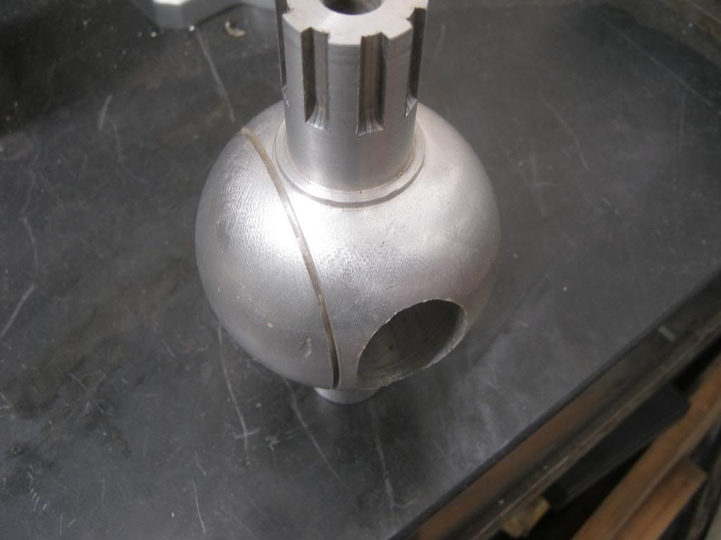
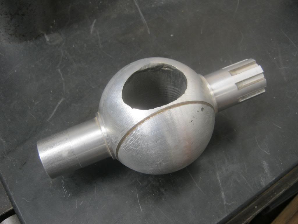
    Also there is this...
    Havent really read the detail but the pics reflect what i found on the RM250...
    http://www.google.com/patents?id=iks...page&q&f=false
    Quote Originally Posted by Frits Overmars View Post
    The port in the cylinder casting has a timing of 196°. Then the upper edge receives a radius that lifts the timing edge to 202°. It's as simple as that.
    Quote Originally Posted by Ocean1 View Post
    Yes, a deliberately rounded edge to the top of the port at the cylinder wall. Gas flows differently at different speeds, it'll follow the curve at some velocities, not at others. You can use this to effectively alter port timing over the rev range.
    Page 600

    Quote Originally Posted by TZ350 View Post
    Page 600 B

    It seems that at high rpm and part throttle the pressure in the cylinder is higher than in the crankcase when the transfers open and hot burnt combustion gases back flow down the transfers.

    Part throttle detonation is the current big issue for our 30+hp aircooled engine. Retarding the ignition on part throttle is only part of the solution.

    More blowdown time area is required to lower the in cylinder pressure so opening the power valve further when closing the throttle at high rpm could be a solution.

    Or the pressure inside the expansion chamber (and cylinder) could be lowered by having a second stinger pipe with a butterfly. Which is opened in high rpm part, throttle situations to drop the expansion chamber and cylinders working pressure.

    And Frits proposes an idea where the intensity of the reflected wave is reduced by changing the size of the bleed venture at the end of the reflective cone.
    Page 606

    Quote Originally Posted by wobbly View Post
    I believe the big radius at the bore centre line has two effects.
    Firstly is to improve the bulk blowdown flow at low opening angles of the piston controlled port orifice, due to the gas attaching early to the roof.
    Secondly the exiting wave amplitude is lowered and smoothed out by the gradual ( instead of a sharp edge ) port opening.
    This would improve the scavenging action bandwidth, but the peak value is probably then raised as well,simply because the port opens earlier when the pressure above the piston is greater.
    Thus you get the best of both, a wider effective scavenging action, combined with a higher peak value, making the pipe work better over a wider range.

    The big radius can only be applied to a port with the chrome removed, it then has to be replated to permit the ring to run on a hard surface as it bulges out into the port - unless of course you have an iron bore..
    Page 607

    Quote Originally Posted by wobbly View Post
    In all the engines I have done the area at the flange face is approx equal to the main port effective area, or approx .75 of all 3 ports. The header diameter is equal to the effective total of all three ports.
    Page 610

    Quote Originally Posted by Frits Overmars View Post
    The only difference is the end cone restrictor diameter: it's 23.3 mm for the 102 and 23.0 mm for the 106 (or the other way around; I can never remember which is which). One was for the 125 cc and the other was for the 250. As the 125 is on full song for a much greater part of the track than the 250, the restrictor difference should compensate for the EGT build-up. Personally I would never go below 23.3 mm with that kind of horsepower.

    Thanks for the warning. Aprilia switched from NGK to Denso because parts of the isolator fell into the cylinder. Now they have switched to Superbikes .
    Quote Originally Posted by dinamik2t View Post
    I think the 102 has 23.3 restriction, based on the schematic in your files, Frits.
    Quote Originally Posted by wobbly View Post
    Have to reduce the Aprilia power output to down around 40 Hp to fit a 22.3 nozzle Frits.
    Quote Originally Posted by ief View Post
    Wob, are you saying you put that in engmod and got det warning when going higher then 40 hp when using 22.3 mm?
    Quote Originally Posted by wobbly View Post
    I did a huge testing project a few years ago on Honda CR125 for SKUSA box stock racing in karts.
    22mm was as small as I could go sitting dead on 40 Hp at the gearbox,going lower made it finicky to tuning and made no more power - 22.5 made less power.
    Although the pipe is a tech item I was able to hide a "tailpipe nozzle " easily enough for testing and racing.

    But also from experience that is about the limit on power and tailpipe nozzle size in all sorts of applications.
    Quote Originally Posted by wobbly View Post
    The pipe does indeed have a silly header, but the angle is close to what the second stage of a 2 stage header would have.
    It then extends into what would normally be a shallow first diffuser cone.
    The result is that the main diffuser is pretty steep, so its this that is giving the good depression around BDC - and the reasonable power delivery at that rpm.
    The Aux ports are giving good blowdown , as there is only a small pressure rise when the transfers open.
    So many small details affect the real power delivery, and I would have to write a book with 30 chapters to even begin to point you in the right direction
    as far as correct assembly is concerned - and its this, that my customers are paying for.
    Page 613

    Quote Originally Posted by TZ350 View Post

    I have just received another Knock Gauge, this one has two extra outputs. http://www.knockgauge.eu/content/blogcategory/22/41/

    YouTube links showing the Knock Gauge in action.

    The two green lights, the orange warning light then you see the red det light. http://youtu.be/aZkZR-JBr_E and http://youtu.be/vFoZyw_sHmA

    Like last time, one that goes to ground for signalling the IgniTec to retard and a new one that pulses from 0V to +5V each time the Knock Gauge sees a detonation event.

    The Curtis event counter can then count the detonations. Now I have the makings of a det sensor, ignition retarder and det counter.


    This post links back to various cheap counters that could be used with the Knock Gauge.
    Page 616

    Quote Originally Posted by wobbly View Post
    Running a KT100 is fraught with heat problems, as it affects every part of the testing.
    Simply put, you MUST have the same head temp and case temp at the start of every test.
    Then monitor the egt at the end of each test.
    For example you can change the pipe length, run up the engine to get your reference head and case temp.
    But the egt at peak rpm may be 100* lower.
    So you must then turn the tap and change the jetting.
    This then means repeat the test, until you reach the same egt as previously.
    Then overlay the curves to see if the new pipe length actually is better than the last one.
    All you are doing is replicating what would happen on the track,but making very sure the conditions are perfectly equal.
    This enables the 1/10 Hp resolution in changes to be seen with confidence, as head or case or egt temp has a way bigger influence on the dyno power reading, than any pipe or small port timing change would ever produce.

    Same issue with a water cooled 125.
    If the change produces a change in egt, then you must go back and rejet and rerun the test.
    On track we will always be shooting for a reference egt,by changing jets based on the current air conditions,no matter what the port timing or the ignition curve or the pipe shape,may be.
    So the dyno result must reflect this process to be able to document on track reality and thus performance, with any useful accuracy.
    P624

    Quote Originally Posted by wobbly View Post
    The pipe is a complete mess both % wise and taper wise - not even close to being too steep - as an Aprilia pipe is 124 or so diameter.
    And expecting an engine to make serious power up at 14,000 with a 196 Ex port is a "pipe "dream.
    The dip in power is due to a big mismatch in spec,that is synergistic at some points , but self cancelling at others.
    P625

    Quote Originally Posted by TZ350 View Post
    Some of Blairs thoughts on the important features in an expansion chamber.

    I have been wondering about the static working pressure inside an expansion chamber but I did not see the answer there that I am looking for.

    Clearly in a well tuned engine the pipe is at the right internal working pressure around peak torque, but does it continue to build up as the revs climb? And if it builds up, is high internal pipe pressure one of the things that stifles the torque curve on over rev.

    Certainly reducing the pipes internal pressure on low throttle openings is a good way to avoid detonation during overrun into a corner or just trickling around the track.

    So now the big question is, can we also get more over rev by moderating the working pressure in the expansion chamber?
    P627

    Quote Originally Posted by wobbly View Post
    You know very quickly if an aircooled is thermally limited.
    The power fades very quickly, and can be seen even doing an all gear run on the inertia dyno.
    I spent 6 months testing pipes for KT100, and it was easy to make around 20 Hp, but this would drop 2 secs a lap as soon as it got hot, ie 2 laps.
    You had to wind in fuel to cool it - not make power.
    I ended up searching for power band width, pumping up the bottom end and overev power, keeping the peak well suppressed to prevent the power fade from affecting lap times.
    Ive sold over 2000 of those pipes now, and so far no one has bettered them on track.
    P631

    Quote Originally Posted by wobbly View Post
    Unleaded fuel to make best power likes to be rich and have plenty of advance with low com.
    Thus in general a shorter pipe would be needed, as you say due to the lower egt.
    But as usual there is a fly in the ointment in that the FIM race fuel that needs gloves and a respirator, acts differently, and ends up with the same tuned length as was used with ELF124.
    But the bulk pipe temp isn’t what the egt probe reads in the header, its the average temp and is alot lower overall.
    Quote Originally Posted by dinamik2t View Post
    Ok Wob, thank you. Is there a way of tricking EngMod into predicting the right rpm for top power, when using unleaded fuel? So far it seems to predict the rpm range as if the egt was around 650C.
    Quote Originally Posted by wobbly View Post
    The biggest thing to realise is that the pipe wall temp seems to work best in the 0 to 100*C range.
    I use 50* for most engines running on Avgas.
    This is a fudge that Neels hates but works very well.
    P655

  3. #10938
    Join Date
    12th March 2010 - 16:56
    Bike
    TT500 F9 Kawasaki EFI
    Location
    Hamilton New Zealand
    Posts
    2,877


    Put a ball valve in the head, uniflow charge, water cooled valve, independent timing ( can be changed on the fly ) , more transfer time area available ( no exhaust port in the cylinder wall ), cooler running piston. Note this valve has piston ring type seal, reacts to pressure as a piston ring would in a round bore. This is a crude welded version it would need ceramic or some trick to keep the heat out of the valve I think? Or not, perhaps water cooled would be enough.

  4. #10939
    Join Date
    12th February 2004 - 10:29
    Bike
    bucket FZR/MB100
    Location
    Henderson, Waitakere
    Posts
    4,230
    There's bound to be a reason why not, but, if you were going to a uniflow arrangement why not make the ball valve control intake which is nice and cool and have the ex ports in the cylinder. You could have all the blowdown you need easily and with modern electronics you could reasonably easily alter the rotary valve timing. Of course you'd still have to overcome all the old problems that have plagued rotary valves like sealing and dealing with combustion pressures while rotating. I envisage a twin cylinder with the cylinders side by side but facing opposite. Pistons rise and fall together, but in opposite directions, and each crankcase feeds the other cylinder rotary valve. Each rotary valve driven from the adjacent cylinder's crankshaft and a gear train between the cylinders with power takeoff anywhere handy.

  5. #10940
    Join Date
    12th March 2010 - 16:56
    Bike
    TT500 F9 Kawasaki EFI
    Location
    Hamilton New Zealand
    Posts
    2,877
    Picture please.

  6. #10941
    Join Date
    20th April 2011 - 08:45
    Bike
    none
    Location
    Raalte, Netherlands
    Posts
    3,396
    Quote Originally Posted by Flettner View Post
    Put a ball valve in the head, uniflow charge, water cooled valve, independent timing ( can be changed on the fly ) , more transfer time area available ( no exhaust port in the cylinder wall ), cooler running piston.
    Been there, done that, 30 years ago. Well, almost; while a friend of mine, Alex Hofmann, built a four-stroke head with two hollow rotating ball valves (first picture),
    I designed a cylinder head for a Yamaha TZ350 twin with a conical Aspin valve above each cylinder.
    Each valve had two diametrically opposed windows that gave access to either the two exhaust ducts per cylinder head or the two spark plugs per cylinder head.
    This symmetry made for a good balance of the valves but also necessitated that they rotated with half the crankshaft rpm. This in turn meant port opening was much too slow for a decent blowdown angle.area. I solved this problem by varying the valves' rotating speed: slow when the exhausts were fully open (BDC) or fully closed (TDC, with the advangage that compression and combustion forces did not cause so much friction losses) and fast in-between. This was accomplished with a train of noncircular gears between crankshaft and valves. All rather complicated; everything had to be lubricated as well.
    Maybe now you'll understand better why I keep saying KISS: keep it simple, son.
    Attached Thumbnails Attached Thumbnails Click image for larger version. 

Name:	Hofmann-4.jpg 
Views:	122 
Size:	265.1 KB 
ID:	279737   Click image for larger version. 

Name:	Aspin valve.jpg 
Views:	118 
Size:	60.6 KB 
ID:	279738  
    Attached Images Attached Images  

  7. #10942
    Join Date
    18th May 2007 - 20:23
    Bike
    RG50 and 76 Suzuki GP125 Buckets
    Location
    Auckland
    Posts
    10,516
    Changing ratational speed with non circular gears, now thats very clever .....

  8. #10943
    Join Date
    20th April 2011 - 08:45
    Bike
    none
    Location
    Raalte, Netherlands
    Posts
    3,396
    Quote Originally Posted by TZ350 View Post
    Changing ratational speed with non circular gears, now thats very clever .....
    Almost as clever as thinking a little longer and going for simple piston-controlled exhaust ports .

  9. #10944
    Join Date
    24th July 2006 - 11:53
    Bike
    KTM 1290 SAR
    Location
    Wgtn
    Posts
    5,541
    Quote Originally Posted by TZ350 View Post
    Changing ratational speed with non circular gears, now thats very clever .....
    Is a very cute trick, eh? Not quite as easy as it might seem though, in theory the tooth profile changes as the radius does. I've got a wee plugin in a CAD app that generates the gears automatically, can't do the variable tooth profile though.
    Go soothingly on the grease mud, as there lurks the skid demon

  10. #10945
    Join Date
    18th May 2007 - 20:23
    Bike
    RG50 and 76 Suzuki GP125 Buckets
    Location
    Auckland
    Posts
    10,516
    Quote Originally Posted by TZ350 View Post
    I know that maintaining a working pressure inside the pipe is important and that to much pressure will overheat the piston. I know it’s controlled by the stinger/nozzle dimensions but I don't understand the actual function of this internal pipe pressure. I would love to know more about what it does and how and why, if anyone can enlighten me I would be grateful.
    I feel I understand the sucking and plugging action of the dynamic pressure wave in an expansion chamber but I would be very interested in knowing more about the function of the static (or average) pressure system that exists in the pipe as defined by the stinger/nozzel pressure blead.

  11. #10946
    Join Date
    12th March 2010 - 16:56
    Bike
    TT500 F9 Kawasaki EFI
    Location
    Hamilton New Zealand
    Posts
    2,877
    [IMG][/IMG]

    Frits, thank you for answering my post. It's me ( uniflow ) If you remember, I'm responsible for this variable rotary valve housing. Don't worry I can take simple and make it complicated!
    This ball valve has never been finished although one day I would like to try it. The key to it's potential success is the round piston ring that seals like a piston ring in a cylinder, seals on a round surface. Originally I was going to use oval gears like you have shown but then decided to occillate the valve. This gives you fast / slow and only one ring is required also the ring gap need never pass over the port. Ring gap would be at 90 degrees to the drive shaft. As you would I'm sure know uniflow offers clean combustion every cycle. Although my 440 uniflow engine ran well it was complicated and sooner or later ( as BMEP rose ) exhaust piston would be a thermal problem.

  12. #10947
    Join Date
    27th January 2011 - 11:30
    Bike
    RS125, TZ80, RS50, RS50, FXR
    Location
    AKL
    Posts
    908
    I'm just going to put this (blasphemy?) here...
    http://page.auctions.yahoo.co.jp/jp/auction/165511282

    MD250 Moriwaki. Based on RS125 as sold by Honda with CRF150R engine instead of the 250 they otherwise come with

  13. #10948
    Join Date
    20th April 2011 - 08:45
    Bike
    none
    Location
    Raalte, Netherlands
    Posts
    3,396
    Quote Originally Posted by Flettner View Post
    Frits, thank you for answering my post. It's me ( uniflow ) If you remember
    I sure do. I'm just wondering now: should I address you as Flettner, as Uniflow or simply as Neil? In any case, I will take this opportunity to compliment you on your projects. The variable rotary valve housing is clever, I like your EFI, and your uniflow engine is impressive.

    Don't worry I can take simple and make it complicated!
    You don't happen to have Italian roots, do you?

    This ball valve has never been finished although one day I would like to try it. The key to it's potential success is the round piston ring that seals like a piston ring in a cylinder, seals on a round surface. Originally I was going to use oval gears like you have shown but then decided to occillate the valve. This gives you fast / slow.
    Fast / slow is the direction to go, but for really turbulent-free flow you would need 'very fast / stop', with the channel through the ball in line with the stationary parts of the exhaust duct. But then the acceleration forces would become huge.
    Maybe you could take another look at Alex Hofmanns four-stroke head; for each 'valve' he uses a hollow sphere that intersects the stationary duct; the part of the duct inside the sphere is also stationary; good for flow and for keeping heat away from the sphere.
    Still, for uniflow I would prefer piston ports for both transfer and exhaust. But I have to agree that cooling the exhaust piston would require a brain wave.
    Attached Thumbnails Attached Thumbnails Click image for larger version. 

Name:	Hofmann-1.jpg 
Views:	78 
Size:	238.9 KB 
ID:	279830   Click image for larger version. 

Name:	Hofmann-2.jpg 
Views:	76 
Size:	244.5 KB 
ID:	279831   Click image for larger version. 

Name:	Hofmann-3.jpg 
Views:	70 
Size:	263.9 KB 
ID:	279832   Click image for larger version. 

Name:	Hofmann-4.jpg 
Views:	91 
Size:	265.1 KB 
ID:	279833  

  14. #10949
    Join Date
    4th January 2009 - 21:08
    Bike
    YLR150RR and a RD350LC
    Location
    Not far from Ruapuna
    Posts
    2,368
    Quote Originally Posted by Frits Overmars View Post
    But I have to agree that cooling the exhaust piston would require a brain wave.
    Would a sleeve valve work in this application?
    My neighbours diary says I have boundary issues

  15. #10950
    Join Date
    26th April 2006 - 12:52
    Bike
    Several
    Location
    Hutt Valley
    Posts
    5,125
    Quote Originally Posted by Frits Overmars View Post
    Maybe you could take another look at Alex Hofmanns four-stroke head
    Thanks for posting this, it's really cool.

    I spent ages dreaming up similar ideas when just out of school, I'm sure many of you are the same.
    To actually see someone try and build on is very, very cool.
    Heinz Varieties

Thread Information

Users Browsing this Thread

There are currently 31 users browsing this thread. (0 members and 31 guests)

Posting Permissions

  • You may not post new threads
  • You may not post replies
  • You may not post attachments
  • You may not edit your posts
  •