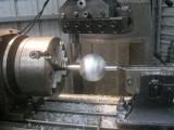
You don't need a CNC to make a ball valve.

 Forum whore

You don't need a CNC to make a ball valve.
Bucket Racer/Crasher
and the housing for it?? So that's what you have been busy with all week.
Anorak

No need to bite Rich, it was only an observation. I pm'd Rich the old pics of the smallest tightest track. here is the updated one.Originally Posted by richban

It about 2 km away, but on the wrong side of the river.

Kinky is using a feather. Perverted is using the whole chicken
Forum whore
I will be making the housing on the CNC ( already have the program) but you could also make the housing by tilting the dividing head at 45 degrees, turn the tool around and generate the inside shape.
Hardcore Biker

It looked strange for a plain capacitor discharge signal, but I have been wrong many times so I stopped making assumptions -publicly- about things I cannot explain.
Still, the manufacturer reports a "DC-CDI" ignition control...
Would you have any bibliography on ignition systems to suggest me speedpro?
Cheers
Bogeyman
You can make almost a full hemisphere on a lathe by making a tierod/link arm and pinning it between the locked tailstock and the cross-slide. Pays to address whatever backlash issues you've in the topslide feed first. I've got an adjustable length one somewhere around here...
Go soothingly on the grease mud, as there lurks the skid demon
Bucket Racer/Crasher
The DC part would suggest battery powered rather than stepping up the AC from a generator and the CDI part suggests exactly what it says. Could be the marketing guys got a hold of it before it went out the door though. I think the late '70s when CDIs and transistorised ignitions were coming in that there was some confusion with labelling. I seem to recall seeing something similar on Kawasaki electronic ignitions for the Zs where a quick measure of the coil primary resistance indicated it wasn't CDI at all. I pissed with this quite a bit and built my own battey powered CDI which was triggered off the points on my AC50 bucket racer. At max spark rate using a signal generator to trigger it the current draw was about 10A but it threw a 10mm FAT blue spark. That was about 40,000 sparks/min with absolutely no loss of output.
Forum whore
I made one of those too, melt tar seal at 10 Km's! Not to be touched. I put more capacitors in it.
Bucket Racer/Crasher
Me and a mate built one each. We upped the voltage from the inverter to the capacitor from 300V to 400V and fitted 2 capacitors for good luck. It wouldn't have been a good idea to touch the primary let alone the secondary. My Ignitech throws a good spark, better than Rob's from memory, but it isn't close to the one I made.
Scooter boy

Minor point to remember when going to a better ignition (for those to whom it applies): bigger spark = more torque (compared to a crap ignition) = more fuel required. Jet up.
Forum whore
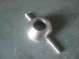
A 32mm ball valve inner, 8mm shafts, ball dia 68.
The home made CDI I built now is used to strobe my injectors. I've coupled a spare coil the the injectors power wire and zippy tied this coil to the coil that triggers the CDI. So when we get an inductance change ( injector powered up or down ) there is enough inductance to trigger the CDI and run a strobe light. Interestingly by changing the polarity on the trigger coil I can " see " injector on, or injector off. Crude but it works great!
Forum whore
http://www.ecotrons.com/2_Stroke_Sma...e_EFI_kit.html
I have been trying to figure out how to go about the initial mapping of my 2-Strokes EFI as I want something that is at least close to the ball park, to kick the whole EFI tuning process of with.
First up I need to build the Speed Density map which plots VE (volumetric efficiency) against RPM and MAP (manifold absolute pressure). The big problem is, VE data is not all that easy to get.
But they say you can determine VE from dyno data which is handy because I have a virtual dyno, EngMod2T.
Not to sure about what I am doing, so rightly or wrongly, this is how I have gone about it.
At the moment EngMod2T does not give a VE (volumetric efficiency) vis MAP graph but it does plot DR (delivery ratio) which is basically VE at atmospheric pressure. So I simulated a whole lot of runs at various atmospheric pressures to simulate changes in MAP to see if the engines VE (DR) changed with changes in pressure.
It didn't much, which is no surprise really as the DR or VE is just a ratio between whats theoretically possible at that pressure and what happens in reality. As the pressure changed the proportion of inside air to outside air remained much the same.
But of course the Power dropped of with decreasing atmospheric pressure (simulated MAP).

Because the Speed Density map is more about the lower RPM range I broke the standard atmospheric pressure DR graph into two parts and maximized the scales so I could see them better.
I made up a spread sheet using the DR values at Standard Pressure (1013) and proportioned them across the pressure range from 300 to 1050.
This is the Formula I formulated. (Actual Pressure / Standard Pressure) * Delivery Ratio ... for each RPM/MAP point.
And entered the values into the EFI's 16 x 12 Speed Density map.
Nice picture, I have no idea what the colors mean. But if you look along the blue edge you can see it pretty much mimics the DR (VE) EngMod2T graph. Hopefully that means I have got something right.
Only Lambda, Load, and Alpha-N maps to go.
Forum whore
Flettner that's very nice work.
I am looking forward to trying the new Ball Valve, old Plenum, and modified OKO "24mm Carb Equivalent" and EFI combo with my new better Blow-Down STA cylinder designed using EngMod2T.
Forum whore
Why???? ....... your making good power, why resurrect the old plenum idea again.
Forum whore
Why not, now it will work without fuel entering the plenum chamber thanks to EFI. As I always say, if some is good, more must be better.
There are currently 4 users browsing this thread. (0 members and 4 guests)
 Posting Permissions

 Reply With Quote

Bookmarks