I think it is more port specific. Re the step. When mulling it over with Kevin he said to off set the header were the flow is slowest. So on an FXR thats the bottom. I have spoken to Team GPR a few times about making an insert for the head. Sounds like its on the product list. Also a lot of people think that you can just weld any old shit together really badly when it comes to 4 stroke exhausts but really they need just as much love as a well built 2 stroke chamber with super smooth transitions and no lumpy shit inside the pipe or even more so the muffler. Love your exhaust people and it will love you back.
Edit: Not sure about your low revving Scooter mike.
Now back to the proper topic. Can't wait to get my NSR umm 300 going in the next month. North island national rounds are the target. Word on the street is the there will be a few Bucket races taking there normal on track rivalry to F3. Or Super buckets as I like to think of it.
ah four strokes.
The FXR exhaust port has some nice flats top and bottom as standard. The flat bottom of the exhaust port floor aids flow out of the head (further improved by extending into the header?). The flat top of the exhaust port is for AR, this should not be extended/blended into the header. Nothing new here but it seems to be so commonly over looked with those big hucked out exhaust ports matched to the headers. Whats really missing are those fantastically loud megas!
I think Mike was asking if that trick would work on smaller engines, you know , ones around 150cc
Don't you look at my accountant.
He's the only one I've got.
On all 4Ts with crap short turn radius flow, having a step at the bottom of the pipe/head face helps to prevent reverse flow backing up into the port where the flow
velocity is least due to turbulence.
You could also look into making a reverse flow kill canister in the first part of the header, this was something I built years ago for FF1600 and was copied later by a couple of USA manufacturers.
Look for pics online of FF headers with small canisters about 150mm from the head, where the first step up is made in a 3 step design.
Next experiment is a sort of "boost bottle " setup in the header as well, this emulates the small crossover pipes seen on Yoshi headers on older Superbikes.
This also kills the reversion wave that runs back up the Ex port during TDC overlap and is so bad in some cases as to be able to see black exhaust residuals inside the first part of the inlet valve port.
The idea was confirmed to work very well ( way better than crossovers ) in a Doctoral thesis I supervised at Cant Uni,using Fluent to 3D model a FF1600 for Mr Evans.
Ive got a thing thats unique and new.To prove it I'll have the last laugh on you.Cause instead of one head I got two.And you know two heads are better than one.


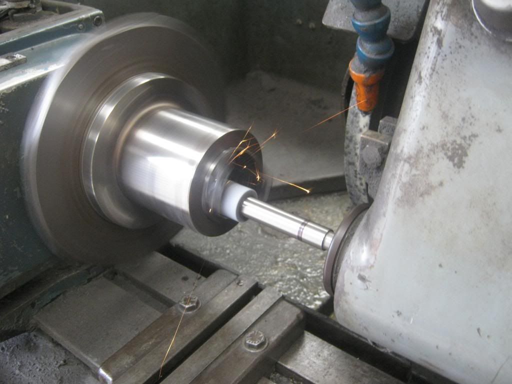
Grinding the sleeve, fixture has been made to hold the sleeve evenly all around.

Yea well Fluent & Guzzi = dinosour on both counts.
Idiot minds working the same again I see Frits.
The FF1600 system with the reversion step, the cannister and 3 step headers, venturi collector with a tapered secondary and "cheater " megaphone muffler
is still by far the most powerful anyone has seen here measured on an independent ( Marsh ) engine dyno.
The PhD canditate wrote a huge program to test every variation of cam timing and pipe design combination I could dream up, of course it won the National title, but has funnily dissapeared since.
Ive got a thing thats unique and new.To prove it I'll have the last laugh on you.Cause instead of one head I got two.And you know two heads are better than one.

Did he get his doctorate?


An oldie but a goodie....doesn't this all sound rather similar to the bit Wob posted a while back about how a yamaha tech solved the detonation problem by putting a boss for a sensor in pretty much the same place...The more things change etc etc...
Wob - I'm pretty sure I was told that that FF motor finished up scattered over ruapuna.
Ok .....
I dusted off my old valve powered signal generator and oscilloscope.
And brought some science to the problem, and it looks like its not me.
In the advanced calibrations screen there are two injectors with appropriate values.
The throttle is opened and FUELPW1 becomes active.
And the oscilloscope shows output to injector 1
Injector 2's connected.
The throttle was opened until FUELPW2 became active.

But there is no corresponding activity on the oscilloscope for injector 2.
So now I know, activity on the gauges does not guarantee output at the injectors.
My guess is that, the second injector has never been functional, and that would certainly explain the problems I have been having.
Later ......
I tried a really old version of the ProCal software and calibration files, they worked, so its some sort of software glitch in the newer replacement version of the software or calibration file that I received from Ecotrons when I reported the problem with the TPS function on the gauge screen earlier.
At least its good to know for-sure what the problem is but I am annoyed at the effort I have had to go to to sort it out. If it wasn't for this I could have been up and running weeks ago.
Tomorrow I will download the very latest Version of ProCal and see how that goes.
There are currently 11 users browsing this thread. (0 members and 11 guests)
Bookmarks