Page 950 of 2704 FirstFirst ... 4508509009409489499509519529601000105014501950 ... LastLast
Results 14,236 to 14,250 of 40559

Thread: ESE's works engine tuner

  1. #14236
    Join Date
    8th February 2007 - 20:42
    Bike
    TZ400
    Location
    tAURANGA
    Posts
    4,095
    As above a Viton O Ring on the spigot face.I have had the oval to round transition made in alloy 7075 as well as some in simple mild steel.
    Biggest issue is trying to get enough weld far enough into the duct,its a real bitch to get even a tiny Tig into the right places.
    Im about to try some alloy stick welding rods, to build up the intake floor on a poxy Triumph 750 head,so this technique may save a hell of alot of drama.
    The rods are only 3mm thick, so it should be easy to add material where needed, and even if it turns out a bit porous,its the shape that matters.
    Ive got a thing thats unique and new.To prove it I'll have the last laugh on you.Cause instead of one head I got two.And you know two heads are better than one.

  2. #14237
    Join Date
    7th September 2009 - 09:47
    Bike
    Yo momma
    Location
    Podunk USA
    Posts
    4,561
    Quote Originally Posted by wobbly View Post
    As above a Viton O Ring on the spigot face.I have had the oval to round transition made in alloy 7075 as well as some in simple mild steel.
    Biggest issue is trying to get enough weld far enough into the duct,its a real bitch to get even a tiny Tig into the right places.
    Im about to try some alloy stick welding rods, to build up the intake floor on a poxy Triumph 750 head,so this technique may save a hell of alot of drama.
    The rods are only 3mm thick, so it should be easy to add material where needed, and even if it turns out a bit porous,its the shape that matters.
    Try an alloy mig welder with a small torch.

  3. #14238
    Join Date
    18th May 2007 - 20:23
    Bike
    RG50 and 76 Suzuki GP125 Buckets
    Location
    Auckland
    Posts
    10,516
    Page 950 .....

    Its all about Exhaust blowdown...........

    Quote Originally Posted by peewee View Post
    hey wobbly or anyone else. ive seen what happens with insufficient blowdown. is there such a thing as too much blowdown ?
    Quote Originally Posted by wobbly View Post
    Its not so much the issue of too much blowdown per se in an engine spec.

    The real issue is how did the excess blowdown for the planned Hp/rpm actually occur.
    Using a CAD program it is easy to see a mismatch between the STA numbers for any combination of port area and timing.

    If for example we see really big numbers for the EX and Bl STA but a mismatched small Tr STA then the performance will be transfer limited - and we wont see the power as the BL STA would predict..

    Go the other way and we can have big Tr STA and big Bl STA, and this in fact may not be an issue, as in many cases having the TR and Bl correct, but an undersize Ex STA
    will just mean that a clever person has filled in the EX floor and the bottom corner rads to reduce short circuiting.

    This scenario will perform as per the correct BL and TR STA numbers predict.
    What I was going on about the other day was to point out that taking a cylinder with low Tr and low Ex timings and simply jacking it up, will for sure give a useful improvement.

    Simply due to the better timing numbers suited to alot more performance, but having huge 130* transfers and a relatively low 192* Ex points to the engine then being BL STA limited.

    Drop the cylinder and grind up the Ex to get all 3 STA numbers complementing each other,and more power than the simple jack up scenario is a given.

    Click image for larger version. 

Name:	Wob Athena MOD STA.jpg 
Views:	136 
Size:	333.3 KB 
ID:	297807 Click image for larger version. 

Name:	Wob Athena Low Ex STA.jpg 
Views:	113 
Size:	333.5 KB 
ID:	297810

    Here are the STA numbers for an Athena 50 - one with the cylinder jacked up, the other with the same transfers but the Ex ground up to match.
    Quote Originally Posted by wobbly View Post
    Again this is the old story of trying to put specifics onto a huge generality.
    The reed cavity of course is connected to the case, and it depends entirely what the total volume is,as to the advisability of
    filling in the so called dead areas.

    I have found that unlike a full noise rotary valve engine there seems to be no power increase if the case volume is made bigger than a 1.3 ratio when using reeds
    be they direct into the case or cylinder mounted.
    And another generality seems to be that the crappyer the transfer ducts, the ratio should tend the other way toward a smaller 1.4 ratio.

    If the case was too small to start with and you fill the reed cavity dead areas, this will make it worse, and vise versa, but as all the factories are now tending toward making the reed box
    smaller and smaller it would seem that filling the cavities and also filling the volume in front of the reed ( to the point where you would think the flow would for sure be affected badly )
    then I would say its a good thing AS LONG AS YOU ARE MEASURING AND CORRECTING THE TOTAL CASE VOLUME.
    Quote Originally Posted by wobbly View Post
    The term port "effective area " is defined as the port chordal width * height * cosine of down angle,and I have found that getting the exhaust duct exit down to 90% of this actual area gives the best power for a single port in the bore.

    The other scenario of say a tripple port, the duct exit area that is the best, is around 75% of the total effective - and this works out in most cases to be exactly the effective area of the main port only
    ( ie deduct the area of the Aux ports ).
    Pipes need to suck deep at BDC.....

    Quote Originally Posted by wobbly View Post
    This may seem counter intuitive, in that most people think ( wrong ) that when the piston rises it creates a depression and it is this that causes inflow into the case.

    The rising piston may make a piston port lawnmower operate, but the vast majority of bulk flow in a race 2T is caused by the pipes diffuser depression, around BDC - when the piston is very much in the way.

    This negative pressure ratio at the Ex port is then communicated to the crankcase via the transfer ducts, creating flow when the piston is at BDC.
    Quote Originally Posted by wobbly View Post
    Cutting or sleeving headers to do a dyno test, is that simply doing that and trying to analyze the results is completely pointless if you have not measured the pipes beforehand to see what the original design intent was.

    If the header is short to start with, and you then shorten it more, the tuned length may be perfect, but the negative effect from the now silly short header length will overpower any of the good effects of the overall length.

    Conversely if the header was short and you lengthened it, the power increase may be mainly due to now having a " correct " % of header - though the pipe length may be completely wrong for the port timing.
    Click image for larger version. 

Name:	Frits Factors -2.JPG 
Views:	184 
Size:	73.1 KB 
ID:	297806
    Quote Originally Posted by wobbly View Post
    having a header say 28% or 36% of the tuned length will invariably produce huge holes in the torque curve - due to the incorrect positioning of the diffuser.
    Click image for larger version. 

Name:	nice radial angles -2.jpg 
Views:	107 
Size:	21.6 KB 
ID:	297808

    Quote Originally Posted by Frits Overmars View Post
    As we were on the subject of scavenging angles, now would be a good time to write something about the radial angles of the A-transfers.

    Surely a duct with a radial angle of over 20° offers a smaller cross-section to the flow than a duct that enters the cylinder perpendicularly?

    Yes it does. But there are two good reasons to angle it upward anyway.

    First, perpendicular mixture streams coming from the A-ports would collide and slow one another right down. The upward angles provide for less velocity losses and less pressure losses, so despite their smaller cross-section, upward ports may flow as much, if not more, than perpendicular ports.

    (Now you may well ask why the B-ports do not get the same treatment; that is because the central scavenging column, resulting from all incoming scavenging streams together, must not have too much radial velocity, or the loop scavenging will result in a loop-loss into the exhaust).

    Second, there is a thing called scavenging balance (I invented the word for my personal use, so this may well be the first time you ever saw it).

    If you looked closely at the scavenging picture of the MB-cylinder I posted earlier today, you may have noticed that the 'radial scavenging directional resultant'
    had a value of 101,045°. 90° would have meant 'straight up'; more than 90° indicates that the central scavenging column is leaning towards the exhaust side of the cylinder.

    But we don't want that; it is bad for the scavenging of the rear part of the cylinder, and it is risky because it may provoke scavenging losses straight into the exhaust.

    But how can we prevent a scavenging column from toppling over to the exhaust side like the leaning tower of Pisa? Not by pushing against its basis, but by pushing higher up. Hence the radial angle of the A-ports.

    The pictures will tell the story. (If only the Pisa architect had known a bit more about two-stroke tuning....)
    Quote Originally Posted by Frits Overmars View Post
    The sine of this 'axial scavenging directional resultant' is an indication of the scavenging column's axial velocity. If the column moves too fast in relation to the mean piston velocity, there will be severe scavenging losses; if it doesn't move fast enough, the cylinder will not be completely scavenged.
    Pay to follow Frits links to read the whole story.

    Click image for larger version. 

Name:	Toriod Head -2.jpg 
Views:	126 
Size:	190.1 KB 
ID:	297809

    Quote Originally Posted by wobbly View Post
    When you are running big combustion chamber volumes, the plug is way too far from the piston and you need to change to a toroid.
    Quote Originally Posted by wobbly View Post
    Running 98 pump I would go to 13.8 : 1 and no more - this would give you 9.7cc combustion volume or 11.9cc to the top of the plug with a (14mm 3/4” reach) 10 range plug. The 17mm shown is the thread length for the plug to ensure the tip protrudes into the chamber.
    From memory the plug tip also needs to be about 6.5mm from the piston crown.

    Quote Originally Posted by wobbly View Post
    The squish following the piston shape by using CNC is very important if you are pushing the limits with around 50% SAR and very tight squish clearance (0.65mm for a 125 54/56mm bore). This also works together with the sharp edge into the bowl.

  4. #14239
    Join Date
    13th June 2010 - 17:47
    Bike
    Exercycle
    Location
    Out in the cold
    Posts
    5,867
    Quote Originally Posted by wobbly View Post
    As above a Viton O Ring on the spigot face.I have had the oval to round transition made in alloy 7075 as well as some in simple mild steel.
    Biggest issue is trying to get enough weld far enough into the duct,its a real bitch to get even a tiny Tig into the right places.
    Im about to try some alloy stick welding rods, to build up the intake floor on a poxy Triumph 750 head,so this technique may save a hell of alot of drama.
    The rods are only 3mm thick, so it should be easy to add material where needed, and even if it turns out a bit porous,its the shape that matters.
    Jesus Wob - bolt the bloody thing to the biggest heaviest fixture you've got - then pre and post heat it. They warp like an overripe banana.

  5. #14240
    Join Date
    18th March 2013 - 08:20
    Bike
    Suzuki GT500 1976
    Location
    United Kingdom
    Posts
    22

    Exhaust area

    Chaps, my vintage single exhaust port barrel has a very short port (30 mm from piston to exhaust stub), should I be aiming my 90% of area in the barrel or further along in the exhaust manifold?

    Also, reading the fuel posts, I went to mow my grass the other morning and the (plastic) can had collapsed slightly ie a partial vacuum, has the "good stuff" been re-absorbed? If so can't I cool the fuel in storage before use to make it last a bit better?
    Cheers
    Dave

  6. #14241
    Join Date
    5th April 2004 - 20:04
    Bike
    Exxon Valdez
    Location
    wellington
    Posts
    13,381
    Quote Originally Posted by DaisyB View Post
    Chaps, my vintage single exhaust port barrel has a very short port (30 mm from piston to exhaust stub), should I be aiming my 90% of area in the barrel or further along in the exhaust manifold?

    Also, reading the fuel posts, I went to mow my grass the other morning and the (plastic) can had collapsed slightly ie a partial vacuum, has the "good stuff" been re-absorbed? If so can't I cool the fuel in storage before use to make it last a bit better?
    Cheers
    Dave
    Hmmmm, I think you'd need to compress and freeze it, before the process started for that to work.

  7. #14242
    Join Date
    8th February 2007 - 20:42
    Bike
    TZ400
    Location
    tAURANGA
    Posts
    4,095
    I would aim to get the end of the Ex stub at 90%,and I would suspect that the area at the flange face is too big now, so get in there with the tig.
    Re the collapsed plastic fuel can, only way this could happen would be that the RVP of the original fuel was way low,and when you opened and then stored it last the ambient temp was alot warmer.
    Now the liquid has cooled down, its volume has reduced, and with no vapour flash off its sitting with negative pressure in the open space.
    Ive got a thing thats unique and new.To prove it I'll have the last laugh on you.Cause instead of one head I got two.And you know two heads are better than one.

  8. #14243
    Join Date
    20th January 2010 - 14:41
    Bike
    husaberg
    Location
    The Wild Wild West
    Posts
    12,151


    Attached Thumbnails Attached Thumbnails Click image for larger version. 

Name:	kawasaki-h2-flickriver-most-interesting-photos-from-two-stroke-motorcycles-pool-74677.jpg 
Views:	138 
Size:	216.2 KB 
ID:	297547   Click image for larger version. 

Name:	vfuHZsGWYzo.jpg 
Views:	103 
Size:	74.8 KB 
ID:	297548   Click image for larger version. 

Name:	RIC_H2.jpg 
Views:	64 
Size:	112.5 KB 
ID:	297549  


    Kinky is using a feather. Perverted is using the whole chicken

  9. #14244
    Join Date
    18th March 2013 - 08:20
    Bike
    Suzuki GT500 1976
    Location
    United Kingdom
    Posts
    22
    Quote Originally Posted by wobbly View Post
    I would aim to get the end of the Ex stub at 90%,and I would suspect that the area at the flange face is too big now, so get in there with the tig.
    Re the collapsed plastic fuel can, only way this could happen would be that the RVP of the original fuel was way low,and when you opened and then stored it last the ambient temp was alot warmer.
    Now the liquid has cooled down, its volume has reduced, and with no vapour flash off its sitting with negative pressure in the open space.
    Thanks Wob, so no free (or even cheap) lunch with the fuel then.
    How far (in mm) as a rough guide should the reduction to 90% be from the bore? (stroke 57, bore 67) I've not tuned this one yet - grinder to metal this week.

  10. #14245
    Join Date
    8th February 2007 - 20:42
    Bike
    TZ400
    Location
    tAURANGA
    Posts
    4,095
    Its an interesting point about the so called " restriction " point - I havnt tried moving the venturi actually into the duct,though thru a PM one member has failed miserably trying this
    due to lack of room past the header face, but reported it did " work " in EngMod.
    I think the important issue is to have as smooth an area change as you can thru the duct- helping the now smaller return slug to transition past the rising piston into the cylinder space.
    In most older cylinders - TZ350 being the best example, the duct is gradually tapered out to be bigger than necessary,so counterboring and pressing in a sleeve
    as far as is possible is easy enough.
    But for example with the TZ400 I did, the bigger port area needed then matched perfectly with a dead stock duct and header diameter.
    The idea being, I believe,is to reduce the total duct volume, starting at the port by filling the bottom corner radi, thus reducing A port short circuiting,then gradually get a smooth transition
    out to the 90% number where the header slips on.
    Ive got a thing thats unique and new.To prove it I'll have the last laugh on you.Cause instead of one head I got two.And you know two heads are better than one.

  11. #14246
    Join Date
    18th March 2013 - 04:44
    Bike
    75 RD250b, 76 250C , 78 250E
    Location
    Poland
    Posts
    172
    I have read that Yamaha in their 250 model through years changed the ex outlet diameter AC was 37mm then RD LC was 35 and finally Rz250 32mm but I don't know is it 90% .

  12. #14247
    Join Date
    12th March 2010 - 16:56
    Bike
    TT500 F9 Kawasaki EFI
    Location
    Hamilton New Zealand
    Posts
    2,878
    Quote Originally Posted by husaberg View Post


    Are you having me on Husaberg! I've just odered two GSX gearboxes to mate up to my three cylinder gyro engine ( new cases so the gearbox and engine are one, 1050cc ). Water cooled, water cooled crank case, case reed, power valve, reverse turning crank. I was thinking of dressing it like an H2 sort of. Frame is chrome molly tube, ladder type, wire wheels.
    Two engines are taken already.

  13. #14248
    Join Date
    20th January 2010 - 14:41
    Bike
    husaberg
    Location
    The Wild Wild West
    Posts
    12,151
    Quote Originally Posted by Flettner View Post
    Are you having me on Husaberg! I've just odered two GSX gearboxes to mate up to my three cylinder gyro engine ( new cases so the gearbox and engine are one, 1050cc ). Water cooled, water cooled crank case, case reed, power valve, reverse turning crank. I was thinking of dressing it like an H2 sort of. Frame is chrome molly tube, ladder type, wire wheels.
    Two engines are taken already.
    No....... I posted the pic of the GSXR H1 cause I thought it was cool
    http://www.kiwibiker.co.nz/forums/at...8&d=1401098239
    the one with the NICE""pipes I posted to give Wob some welding hints lol.
    http://www.kiwibiker.co.nz/forums/at...7&d=1401359372
    still cool bike though
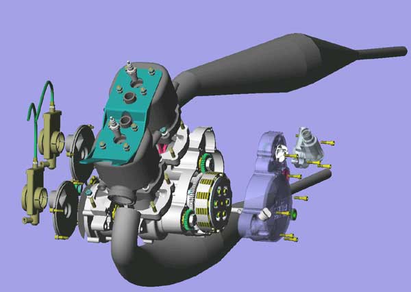
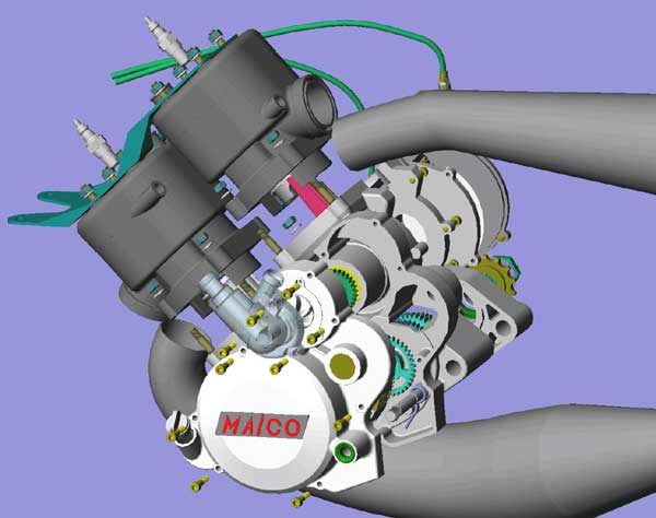
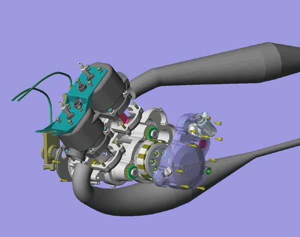
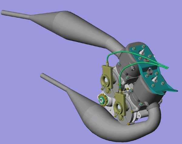
    the Maico CAD cause it was purrty


    Kinky is using a feather. Perverted is using the whole chicken

  14. #14249
    Join Date
    26th April 2006 - 12:52
    Bike
    Several
    Location
    Hutt Valley
    Posts
    5,125
    Quote Originally Posted by husaberg View Post
    the one with the NICE""pipes I posted to give Wob some welding hints lol.
    http://www.kiwibiker.co.nz/forums/at...7&d=1401359372
    I feel better about my mess after seeing that.
    Heinz Varieties

  15. #14250
    Join Date
    18th May 2007 - 20:23
    Bike
    RG50 and 76 Suzuki GP125 Buckets
    Location
    Auckland
    Posts
    10,516
    Click image for larger version. 

Name:	5A Generator 003.jpg 
Views:	42 
Size:	132.2 KB 
ID:	297567

    I need 5.5Amps to run the electrics on the EFI bike.

    Ignitec ignition, Power Valve Servo, EFI fuel pump, EFI Cpu and the four channel temperature data logger.

    Not being able to find something small that will do the job I have resorted to using an original Suzuki GP125 unit with two 6Volt lighting coils wired in series. Its a very heavy flywheel compared to the KX80 one that I am using now, so not to sure how it will go.

    Click image for larger version. 

Name:	5A Generator 004.jpg 
Views:	50 
Size:	129.6 KB 
ID:	297568Click image for larger version. 

Name:	5A Generator 007.jpg 
Views:	46 
Size:	131.5 KB 
ID:	297569Click image for larger version. 

Name:	5A Generator 009.jpg 
Views:	44 
Size:	130.5 KB 
ID:	297570

    When riding a bike you would not normally get to see it, but on the dyno we were able to check the temperatures of some different flywheels. They were all very hot, to hot to touch.

    This was very surprising and at first we thought there was something wrong, the poles touching or eddy currents or something. But then we checked one that had no generating coils and that was very hot to.

    So the conclusion is that this heat is coming from inside the motors. The next engine is going to have a cooling duct feeding fresh air to the generator cover in the hope of reducing some of the heat in that area. With the idea, that any cooling is good cooling on a air cooled 2T.

    Click image for larger version. 

Name:	5A Generator 010.jpg 
Views:	52 
Size:	140.1 KB 
ID:	297571Click image for larger version. 

Name:	5A Generator 011.jpg 
Views:	49 
Size:	136.8 KB 
ID:	297566

    With the big flywheel it was difficult to find a place for the ignition pickup but this should do the trick.

    I am heading off for a week working in the SI so wont be any more progress for a bit but I am keen to get these projects finished and back on the dyno to see how they measure up.

Thread Information

Users Browsing this Thread

There are currently 14 users browsing this thread. (0 members and 14 guests)

Posting Permissions

  • You may not post new threads
  • You may not post replies
  • You may not post attachments
  • You may not edit your posts
  •