Frits, what sort of physics education/knowledge do you have? Do you follow quant-mechanics for instance?Originally Posted by Frits Overmars


 Hardcore Biker

Frits, what sort of physics education/knowledge do you have? Do you follow quant-mechanics for instance?
Hardcore Biker
Wobbly, what is your rule of thumb for delaying aux-exhust ports?
Hardcore Biker

Looks like Honda tested everything that they wanted. Surprises again - 375cc 3 cylinder engine in 1994, before decide to work with 500 V2 configuration (100 hp at 8000 rpm. and 100 kg. !!!)
Muddler/Dabbler.

I don't often post here as I'm not involved with practical "fine tuning"- wish I could be involved!....... I do look in now and again and
Possibly the only problem (if it is a problem), with this forum is that what you see in the posts doesn't always give the full picture.
I feel that there is some discussion going on in the private messaging, leaving big gaps in the conversation and making it hard to follow - we have all done that of course!
Hope this hasn't gone 'off topic' too much!
Happy New Year.
Strokers Galore!
Moped rider

A bit of Helmholtz...but sticking a bit to the 1st law of thermodynamics , not frequency.
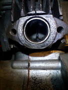
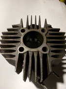
Exhaust flange on air-cooled cast iron cylinder. To improve cooling I've made a cut to prevent heat going from duct/flange to cooling fins i.e. to cylinder. Pipe in the duct was step further, decreasing volume/diameter to calculated one but also adding Air barrier between hot gas and header. Is it the right thing to do? I was debated so much around here but no Dyno to witness. All I know bike was on pipe a bit later.
Hardcore Biker
Is that a Fs 1 cyl, Looks a little rough perhaps? do you have more pics?
Forum whore
The only practical advice re Ex stagger is to look at working examples , and the application.
A TM kart engine ( 54 square ) has a smidge over 1mm , but this is tempered by the fact that they dont use pin plugs and thus cant
grind the Aux around to bore center , nor pocket radius the outer edge to promote flow.
If you lift these to be the same timing you loose 3 Hp at 11,000 ( 10% ) but gain 6Hp at 14500.
This makes the driver moan real loudly about no off corner power - even though lap times are identical.
The RSA ( again 54 square ) had close to 2mm stagger , but those Aux went around to bore center.
That engine had a PV blade as well , so the lower wider Aux combined with the PV must have given the best overall result - on the dyno and on track.
That leads to the obvious question about pin plugs in the TM = + 1.5 Hp at 11,000 not much more anywhere else.
But widen and pocket the Aux and the pin plugs loose nothing against stock at 11,000 , but add the 6Hp back up at 14500.
Now that is a fast engine , even more so when the gearing is shortened to give better off corner drive and just slightly better terminal speed using the big overev.
Ive got a thing thats unique and new.To prove it I'll have the last laugh on you.Cause instead of one head I got two.And you know two heads are better than one.
Moped rider
No, it's not Yamaha, but it is tomos 15SL
Closest to fs1 is jawa90 around here

Hardcore Biker
Thank you Wobbly
Hardcore Biker
Yes I realized no fs1 too late. You have a bridge welded in the exhaust port? I can't see really in the pic but preferably the insert should meet with the duct in a smooth fashion.
Fair weather rider

Ah! Now that can be done in a reasonable workflow by keeping the outer radius constant and using an equiangular spiral for the inner surface. In this position the curve is increasing radius. The parameters for the spiral can be solved for from the entry and exit positions and then intermediate points calculated to generate the spline.
With a bit of work this could be fully parametric to adjust to the exit angle and other dimensions, I think.

Moped rider
Made this cause friend of mine made almost 80% wide exhaust.
The bridge is a peace of cast iron cooling fin, from used cylinder, grinded to have about 5° between lower and upper surface(self locking), exhaust duct machined to match same cone slots up and down the duct, then put the fin into the duct (slots) to enter a cylinder a bit, hammer a bit just to stay in place (which it will cause of self locking angle) then spot weld upper and lower end closest to flange with Ni or bronze electrodes.
Later on cylinder has to be machined to oversize. Bridge was hand grinded in for 0.2 mm.
Tested during 12 trainings and races with approx 24 rhs on it without any issues
Hardcore Biker
Ok, then I understand perfectly.
Forum whore
I'm 70 years old now, so my physics education started about the same time that fire was invented. That came in quite handy if thermodynamics is what you need.
Knowledge? That's simple: it's never enough. No matter what you study, if you're serious about your work, you'll always end up at the boundaries of your knowledge.
Quantum mechanics: I barely follow it; I still hope that one of these days someone will come up with a more elegant approach.
Improving cooling by preventing heat going from duct/flange to the cooling fins?? Yeah, if your goal is to keep the cooling fins cool. But you don't want cool cooling fins, you want all the walls that come into contact with fresh mixture to be cool.
Inserting a pipe in the duct will decrease duct volume and diameter, which is usually a good thing. And the air barrier between the pipe and the original duct will keep the original duct cooler, but it will keep the inserted part of the pipe hotter, which is a very bad thing.
The fact that with this solution the bike comes on the pipe a bit later is an indication that the exhaust gas stays hotter. In itself that is not a bad thing. But the hot inserted part of the pipe will also heat up the washed-through fresh mixture which is bad for power and provokes detonation.
Moped rider
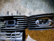
Frits, why would then mostly air cooled kart cylinders, like these two, have flanges as closest possible to the cylinder without any fin attached to the flange? Looks to me that they are trying to cool cylinder as much as possible I.e. on a radial positioned fins like here, heat from flange would go directly to transfer ducts if fins attached to. On that cast iron cylinder of mine fins are axial positioned and no fins from flange are connected to the transfers. Looks like two situations and finally getting some answers!
There are currently 93 users browsing this thread. (1 members and 92 guests)
 Posting Permissions
 .
.
 Reply With Quote

Bookmarks