I think, also taking the gear ratios of TZ's engine into consideration, a plot comparing rear wheel torque through the gears, with both curves geared to the same top speed would be quite handy. That one with the bigger area under the curve, wins.

 Hardcore Biker

I think, also taking the gear ratios of TZ's engine into consideration, a plot comparing rear wheel torque through the gears, with both curves geared to the same top speed would be quite handy. That one with the bigger area under the curve, wins.
Forum whore

Sounds good, but it is not completely accurate because top speed is not decisive. In fact top speed is about the most overrated thing in racing. What counts is getting there first, not fastest; the guy or girl with the highest average speed wins and that is true for all forms of motorsport (trial and motoball excepted).Originally Posted by Haufen

Moped rider

I plotted road force v road speed, mph for both curves, I did use an arbitrary overall gear ratio of 13:1 for the 28 hp curve and 14.4444:1 (13/.9) for the 30 hp curve. For comparison I included power (multiplied by 4 so it's easier to see on the graph) v road speed, mph.
I imagine both curves being used to propel the bike and as I look along the each power curve I try to imagine where each bike would be relative to the other in a straight line. The 28hp bike would set off quicker and go ahead but then the 30hp bike would start to catch up towards the end, not sure if it would pass, i'm guessing it would be close.
Dave
Hardcore Biker
Exactly what I wrote? Gear both to the same top speed, then the potential to get there first = area under the curve(s) of the gear(s).
Bogeyman
I never understood push belts, for exactly the reason you've given. The belt itself must also be a fair bit heavier to resist bending moments. Simple twin variable sheeves, control on the driver and sprung on the driven is not only much lighter but having a natural negative feedback output from any mechanism makes for simpler and more effective control problem. I take it racing scooter CVTs are torque control only, via radial helical slots/balls or similar?
Go soothingly on the grease mud, as there lurks the skid demon
Hardcore Biker
Looks like they'd be pretty close to each other, indeed. The 30hp curve should be easier to drive, because it's torque rises more softly
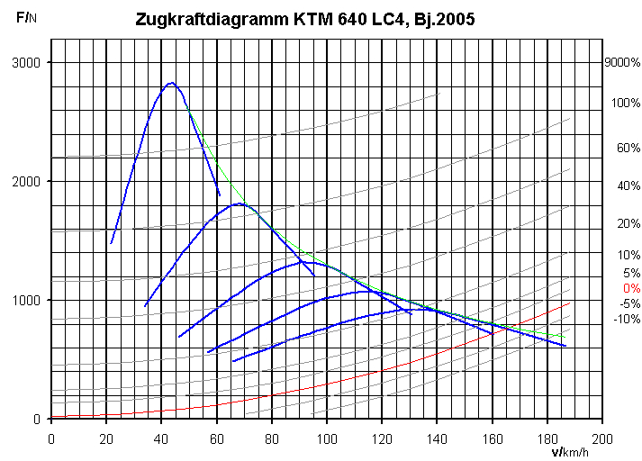
If we knew the gear ratios of TZ's engine, we could even better relate that to real world driving, and, as a bonus, it would give us optimum shift rpm for each upshift. It would look like this:
Forum whore
There is that KISS again! Thankfully we are not interested in selling zillions of scooters. I absolutely agree that a variable speed gearbox is the way forward and have given it much thought, but not built anything yet. I'm still looking at engine variability.
Forum whore

The Beast was fitted with a 1974-76 five speed TS125 Transmission gear set to get away from the ugly gap between 2nd and 3rd in the GP box. I will see if I can find the ratios.
Forum whore
In my opinion having just 5 gears is a major problem. Are you sure you can't get the
TS100/125 six speeder to fit?
Forum whore
We have had a good look at that, its not impossible but the shafts are 12mm longer and it would be a bit of a tricky welding and machining job on both halves of the cases.
Graphed with Combustion efficancy set to 83%
3ex PV in side ports, basic RS pipe.
An easier option may be keeping the 5 speed and making a cylinder with tripple exhaust ports and power valves in the side ports or a CVT system.
OK I found an old Team ESE post about the gear ratios with a GP to TS conversion. The graph was done by TwoTempi.
On Cotswolds thread he is converting a set of 5 speed TS gears for his GP
Forum whore
While not bucket related, a little has been written about this engine here, here is a little extra information
http://www.vincelewis.net/bigengine.html
My neighbours diary says I have boundary issues
Forum whore
TeeZee if your getting into fuel injection there is a whole new language and concepts to learn.
Like “Speed Density” and “Alpha-N”, VE Volumetric Efficiency Table, AEM’s, IAT’s, TPS, VTA and how to use Excel spread sheets for smoothing 3D plots in CSV format.
Something below I scraped of the net to give you the idea……
Speed Density. So after much thinking about how to explain what true Speed Density is vs what we do here for instance, how AEM's are often setup, etc. I came up with the following idea, just explain what everything is and remove doubt.
MAF - if you dont know this one its a volume sensor. Thats it. Ours have IAT and a baro comp to make it more accurate but it simply measures volume entering the engine. If there are boost leaks its inaccurate, doesnt like VTA (letting metered air leave without pulling fuel), all the stuff we know.
Alpha-N - TPS x RPM. That is all that is with no VE compensation (i.e. boost). If I tell it that at 100% throttle and 6000 rpm it does it at all boost levels independent of air volume.
Speed density - estimates air mass by pressure vs temp. Then applies this to a 3D map. The "3D" we already have, its Load (pressure or volume) x RPM with a set value in each cell. Every point can be fine tuned so this is really Alpha N with compensation. Any VE changes needs a retune, doesnt matter the system. It only knows pressure and rpm not what the true mass of the air is (it has a trim table and most get ignored above certain levels).
I use the fuel temp sensor to mimic an IAT since its already in the car. The IAT reads gross temp not average. It can heat soak, be subject to a meth jet to close, all sorts of little issues. The actual trim table in the Evo ECU really isnt setup for IAT trim anyway. It has an algorithm that allows for minor alterations to fueling since its set for a MAF, and then trims timing vs air temp.
Fuel temp is more or less constant. The fuel heatsoaks going thru the rail hits the tank and then is sent forward again. It takes 15 minutes to get full heat into the fuel system (ask anyone with an A1000). It is a rough average of engine bay temp which is what the MAF does factory. I have done exhaustive testing and see no more than 5-6* variation from fuel temp as a source to what the MAF would read in the corner of the engine bay.
Now for the term everyone has been waiting for, Boost Comp. This is what MAFs do, most SD setups (AEM, Motec, Autronic, Vipec, etc.) do for fueling. It assumes VE is more or less constant until you hit backpressure in the turbine housing, head flow, cam size, and VE starts to drop off again.
I set the fueling at 16psi and in our maps this is 180% load or so. The values are constant out to 38psi. Hyper Boost Compensation is the proper name. Retuning is as easy as altering either the max boost portion of the MAPVE table to allow more or less fuel vs pressure, and in some cases the tip in portion of the MAPVE (121kpa column).
There is no such thing as true speed density. I havent seen any AEM ever do this or any other standalone. GM is the closest to True SD and its because tada they use a MAF as well to judge volume vs pressure.
There is also Alpha-N with Boost Comp. This is more or less what we do EXCEPT IT HAS NO TEMP input. It is solely rpm x TPS x pressure. Since we aren't doing fueling by TPS vs RPM at any point other than accel enrichment it is not accurate to call the SD we normally do on Evos Alpha N or N-Alpha or Alpha-Omega or whatever. Alpha N is different and is normally something reserved for ITB cars or quads (single cylinders) that have really non specific fueling and just need fuel vs tps x rpm.
Often we deal with the question, "Which is better speed density (SD) or mass air flow (MAF)". As with most things in life there are advantages and disadvantages for both. Its better to understand each strategy so as to make the most informed decision.
Mass Air Flow
Mass air flow sensor equipped cars fuel either directly from or by a blended model of both mass air flow and speed density calculations. The MAF sensor is located somewhere in the intake stream typically away from sharp bends and typically at least 8-10 inches away from the throttle body however these rules are not always followed. There are several different types of MAF sensors but for most GM applications it is a frequency biased "cold-wire" sensor that generates a signal between 0 and 15k Hz. MAF sensors read not just airspeed but the relative mass of the air which eliminates pressure and temperature as variables. They are usually positioned to sample from the middle of the intake tubing which should give the best average reading.
Since the MAF sensor samples from a specific spot in the inlet tubing changing the airflow in or around the sensor requires recalibration of the MAF sensor. Changing the airflow around a MAF sensor can be caused by a change in size of the intake plumbing, bends before or after the MAF sensor, and changes to the MAF housing.
Several applications that use MAF biased strategies also use Speed Density as a backup or for a blended fuel calculation. They also use Speed Density as a sanity check for MAF readings.
Advantages
Typically more forgiving and easier to tune
If the MAF sensor has been calibrated typically fueling remains consistent as modifications change. It can be said that the MAF equipped cars are a little more forgiving to new modifications
Since the MAF sensor measures air mass directly it can be said that a MAF equipped car might stay in calibration as the engine wears or in extreme environment changes (however this is not normally a concern for well tuned speed density applications).
Disadvantages
Sensitive to changes to the intake plumbing
Can be fouled by becoming dirty. Once fouled MAF calibration is skewed
Sensitive to cam reversion on large cammed cars. The MAF sensor isn't directional so air pulsing back and forth can affect repeatability and reliability.
Limits on performance. Most systems can not read at higher horsepower levels.
Speed Density
Speed density systems calculate the density of the air first by measuring the temperature of the inlet air and manifold pressure. With the density of air known the engine controller then looks up how much air it expects to be moving at a specific engine speed and manifold pressure. This is done in the Volumetric Efficiency table or VE table. Traditionally the VE table is 3D and has two axes Engine Speed (RPM) and Manifold Pressure or % Load. A engine that is 100% efficient moves exactly its displacement every two rotations in 4-cycle engines.
Advantages
Less restriction in the intake tract
More freedom in the intake tract
Able to measure air consumption on very high horsepower builds where a MAF sensor might be limited.
Able to read boost if equipped with a greater than 1 Bar map sensor
Free from errors encountered in MAF fouling.
Works better with large cams where reversion affects reliability.
Disadvantages
Is a little more difficult to tune
Relies on a well tuned Volumetric Efficiency Table
Less forgiving to new modifications to the engine
Might have errors in large weather changes however a proper tune makes this minimal if any error.
There are several vehicles that come with MAF sensors from the factory and there are several vehicles that come speed density from the factory. Really which fueling strategy you should go with on a aftermarket application is up to your modifications goals and expectations. If you are not the one to be tuning your setup please consult with your tuner for what he or she recommends.
Speed-Density is a method of estimating airflow into an engine in order to supply an appropriate amount of fuel and adequate spark timing. First, vocabulary:
ECM, ECU, Engine computer : used interchangeably to mean the computer operating the fuel injectors and running the engine
RPM : Revolutions Per Minute – how fast the motor is spinning
MAP : Manifold Absolute Pressure – (usually) the pressure of air entering the motor
ECT : Engine Coolant Temperature sensor – sensor used to measure the temperature of coolant circulating through a motor. Sometimes called different things by different manufacturers. I will use ECT here
IAT : Intake Air Temperature sensor – sensor used to measure the temperature of air entering the motor. Sometimes called different things by different manufacturers. I will use IAT here.
Displacement : the volume swept by a piston descending from the top to the bottom of the cylinder bore. More here.
AFR : Air Fuel Ratio – the ratio of air to fuel present in a combustible mixture. Usually stated as a ratio, i.e. 14.7:1 for the stoichiometric AFR for gasoline. Stoichiometric AFR varies from fuel to fuel.
Lambda : similar to AFR, except usually expressed as a number where 1.0 represents a stoichiometric mixture for all fuels. Lambda and AFR are the same concept expressed in different units.
Stoichiometric : a mixture containing the precise amount of oxidants required for complete combustion of all fuel present. See here or here for more information on chemistry involved.
Ideal Gas Law : PV= nRT (Pressure times Volume equals moles of gas times ideal gas constant times temperature) More to be read about this here.
Moles : a measure of how many atoms are present. See here.
Induction stoke : the part of a 4-stroke engine’s cycle in which air is drawn into the cylinder by the piston. See here for more information if you are not familiar with a 4 stroke engine’s operation.
Basic Goals and Method
The goal of Speed-Density is to accurately predict the amount of air ingested by an engine during the induction stroke. This information is then used to calculate how much fuel needs to be provided and may also be used for determining an appropriate amount of ignition advance.
The theoretical basis for this is the Ideal Gaw Law (more here.) rearranged to solve for “n” (the number of moles of gas present :
n = PV / RT
In order to use n = PV / RT to calculate the amount of air a motor ingests during the induction stroke we would need:
P is pressure in the cylinder immediately after the intake valves close.
V is volume, which we know from engine displacement.
R we know (it’s the Ideal Gas Constant see here for more)
T is the temperature of the gas in the cylinder immediately after the intake valves close.
Many of the things required to calculate the amount of air the engine ingests using the ideal gas law are missing, unavailable or at least incomplete. Some notable points where reality is less than ideal:
Our MAP sensor measures the pressure differential caused by the downward stroke of the piston in the intake manifold, not pressure in the cylinder as the intake valves initially close.
We are assuming that there is no residual exhaust left in the chamber to contribute to “poisoning” of the intake charge.
Camshaft overlap (i.e. when both intake an exhaust valve are open simultaneously – see here) makes fluid flow modeling considerably more complicated.
T that we need is the temperature of the gas in the cylinder. This is not usually MEASURED – instead it is ESTIMATED from the temperature of air in the manifold (IAT), the temperature of the cylinder heads (ECT) and other factors. “RT” is often referred to as the “density correction term” as it tries to account for how air density varies with temperature. Density correction is arguably one of the biggest problems with speed-density. (more on this later)
Speed-Density introduces the concept of Volumetric Efficiency (VE) to account for the differences between what it can observe and what is really going on. (mostly problems 1-3 above) Roughly speaking, VE is the ratio between the amount of air actually present in the cylinder and the amount of air we predict would be in the cylinder using MANIFOLD pressure (MAP) instead of cylinder pressure for our “P” Pressure term, REVOLUTIONS Per Minute (RPM) times Displacement (Volume / REVOLUTION) for our “V” term and an air temperature value estimated from some combination of ECT and IAT for our “T” term.
A motor said to be operating with 100% VE has the same amount of air actually in the cylinder as predicted by n = PV / RT. Most engines operate at considerably less than 100% VE in most operating conditions. The difference between actual airflow and theoretical maximum airflow is termed “pumping loss.” Some engines (most notably Honda engines) can achieve slightly greater than 100% VE in certain conditions. Most engines operating under forced induction can be thought of to have a VE greater than 100% in some conditions.
Speed Density ECMs generally have one or more VOLUMETRIC EFFICIENCY (VE) tables that are a critical item to be adjusted. These tables allow predicted airflow values to be more closely adjusted to observed reality.
Strengths of Speed-Density
Speed-Density has many things going for it:
Pressure sensors do not pose any restriction to the flow of air into the engine, unlike a MAF sensor.
MAP sensors respond to changing conditions very quickly, enabling it to have fairly good transient response especially compared to Mass-Air-Flow
Compared to a carburetor, it allows much more control over the mixture at different engine loads
Simplicity: all the sensors required are extremely reliable.
Weaknesses of Speed-Density
Speed-Density is known for having several notable issues:
Density correction, density correction, density correction. You might not think that temperature is that big of a deal, but trust me it is! Seasonal changes can wreak havoc on speed-density systems. Superchargers or turbochargers that compress air and raise its temperature from adiabatic heating cause significant changes in density that must be accounted for. Altitude can also be really problematic. Many systems incorporate Barometric Pressure sensors to try to address this, but it’s an imperfect correction.
Large camshafts with extremely low vacuum due to high overlap close to idle. Camshafts that have low or pulsing vacuum close to idle present a challenge for Speed-Density. MAP sensor averaging can help. Alpha-N blending can help. It is still very tricky to use speed density to predict airflow with a pressure sensor with camshafts that do not build an appreciable amount of vacuum.
Volumetric Efficiency tables can be very time consuming to tune.
Engine modifications generally produce volumetric efficiency changes requiring re-tuning.
Quite a lot of math is required to do Speed-Density “by the book.” Because of this, most manufacturers implement something kind of like theoretical speed-density and cut corners or combine math operations in order to allow faster execution on puny computing hardware. (Remember, most ECUs made prior to 2000 have a slower processor than the average inexpensive cellphone circa 2010)
Sanity Checking a Speed-Density Tune
There are a few rules that transcend particular manufacturer implementations:
Volumetric efficiency rarely changes suddenly. VE tables should almost always have very gradual changes.
VE usually DECREASES as pressure DECREASES (i.e. more vacuum = less VE)
VE usually maxes out at an RPM close to peak engine torque at maximum observed load, which is usually where peak cylinder filling occurs.
Remember that VE tables are not the only thing that controls fueling. Temperature correction tables (ECT, IAT) are often implemented as multiplier/divider tables. Don’t forget about injector battery tables either! (see the separate article on Injector Tuning for more on this)
Alpha-N
An Alpha/N table allows the ECU to calculate some sort of output based on any combination of how much the throttle is open (Alpha), and how fast the engine is spinning (N). The Alpha term can range from 0% (closed throttle) to 100% (wide open throttle). The term "N" corresponds to engine RPM.
The two main Alpha/N tables are used to determine ignition advance and fuel injector pulse width. An Alpha/N ignition table would use throttle position and RPM to calculate what spark advance it should be using. Similarly, an Alpha/N fuel table would use throttle position and RPM to decide how long the fuel injectors should stay open.
Throttle Angle
The throttle angle term was tougher to figure out. While the RPM rows were spread out evenly across the operating range, the throttle angle columns were not. There is a good reason though. If you think about it for a minute, a difference in throttle angle is not a simple linear change like RPM. For example, changing the throttle angle from 1% open to 2% open is a huge difference (100%, in fact). Compare that to changing the throttle angle from 90% open to 91% open, which is only about a 1.1% difference. What this really means is that the effects of throttle changes are concentrated mostly in the range of small throttle openings. In contrast, at large throttle angles, the same small changes are almost meaningless. Therefore, the throttle angle, or 'Alpha' part of the table is strongly stacked towards providing lots of information at the end of the scale where the throttle is barely open, and has much less information about situations where the throttle is open fairly wide. This also makes sense when you consider that much of what a rider considers as 'driveability' issues occur when cruising down the road with the throttle barely open. Giving the ECU extra information about part-throttle situations makes for better driveability.
Alpha-N uses the throttle position (alpha) and RPM (N) to calculate the amount of fuel to inject as opposed to using the manifold absolute pressure (MAP) and RPM to calculate the amount of fuel to inject. Alpha-N is useful for long duration cams where the resolution of manifold air pressure (map) would be small.
Manifold Absolute Pressure, then, is just what it says: The absolute pressure which exists in the inlet manifold, usually measured in the plenum (if one exists). The MAP in an engine which is not running is equal to atmospheric pressure. If, on a "standard day", an engine is idling at a measured manifold "vacuum" of 14 inches,, the MAP is actually 15.92 "HG (29.92 - 14 = 15.92).
1 atmosphere = 760 mmHg = 29.92 inHg = 14.7 lb/in2 = 101.3 KPa
Anorak
That's a big post, A lot to take on board, who would of thought that.

Kinky is using a feather. Perverted is using the whole chicken
Hardcore Biker

I think you would be pretty game to try anything other than an 'Alpha-N' setup. Pulsing on a single cylinder will make the engine hunt and low rpm. And MAF will restrict your inlet and is heavy as balls.
And download matlab instead of excel. Much better at dealing with large matrices.
Forum whore
Thanks Bucket and Mooools
To get started, most of the info for VE, Speed Density and Alpha-N maps can be gleaned from the EngMod2T simulations.
Because of the pulsing in the inlet tract that Mooools talked about and which is particularly bad in a 2-Stroke, the Fuel injection system we are getting has a Speed Density map for low RPM and uses Alpha-N for the high RPM end.
I have been told that as an optional add on, it can also have a mixture adjustment with exhaust temperature option. I am not sure how that works but hopefully it means we can give it a target ET and it will maintain it just like Wobbly has talked about for maintaining optimum AFR with changes in conditions during the day.
I am not sure how the injection timing works but the system triggers from the existing ignition pickup. Because I want to inject into the transfers while the are open and flowing, I guess it will be easy enough to fit a dedicated trigger at some other point to get the injection timing right.
Anyway hopefully Chambers and I will have our kits by the end of the week.
There are currently 97 users browsing this thread. (1 members and 96 guests)
 Posting Permissions

 Reply With Quote
 . But if you wish to sell zillions of cheap scooters you have to stick to the KISS principle.
Bookmarks