Balance shaft? Will they take a CR250 gearbox as you can get 6sp boxes for CR's now. Looks good Neil, got my emails back to now.Originally Posted by Flettner


 Hardcore Biker

Balance shaft? Will they take a CR250 gearbox as you can get 6sp boxes for CR's now. Looks good Neil, got my emails back to now.
Why Not???: MNZ975.

Great work. This is very interesting.
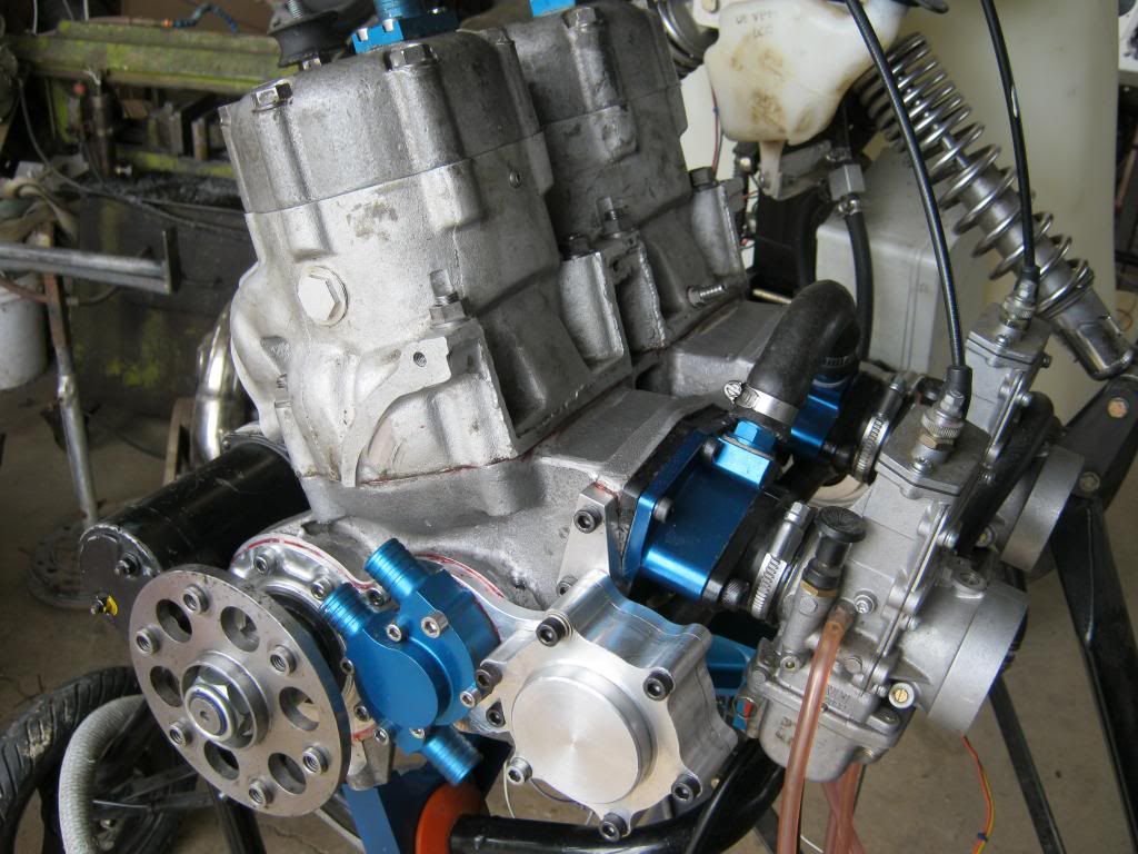
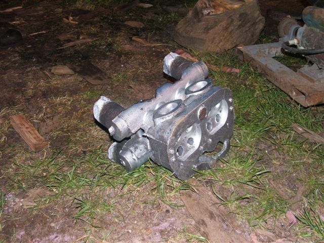
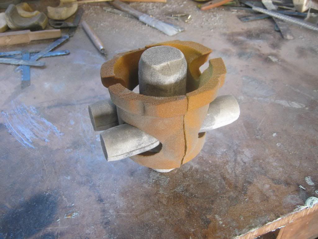
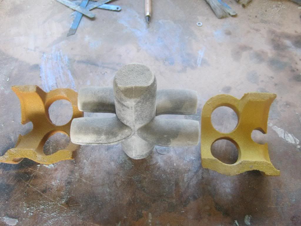
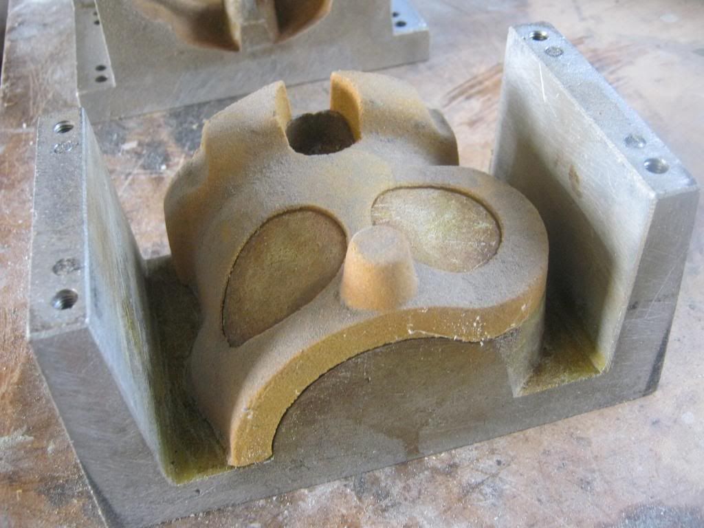
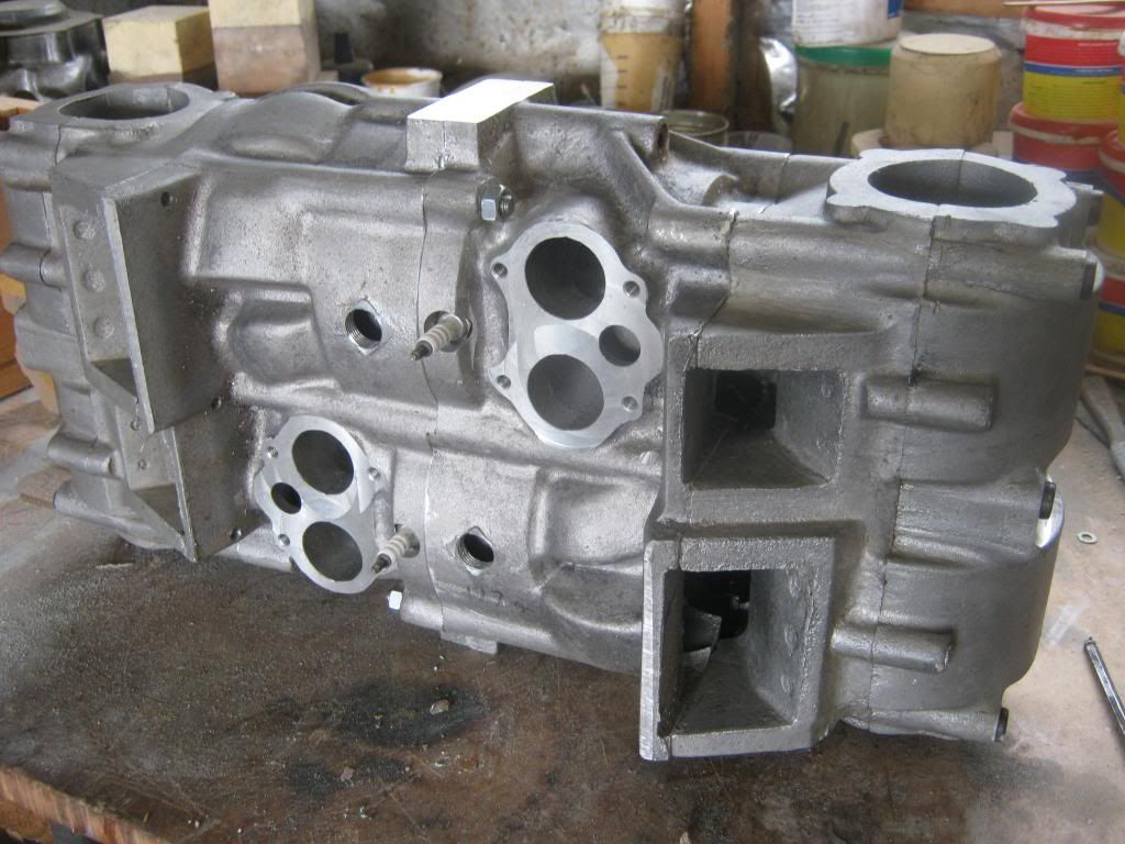
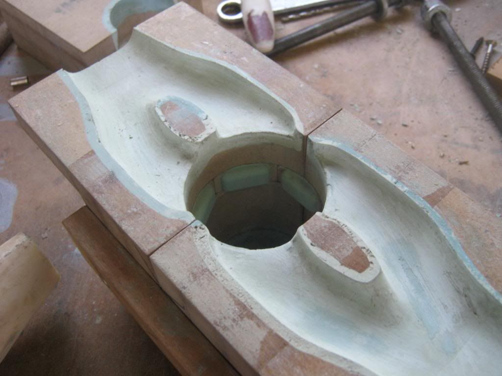
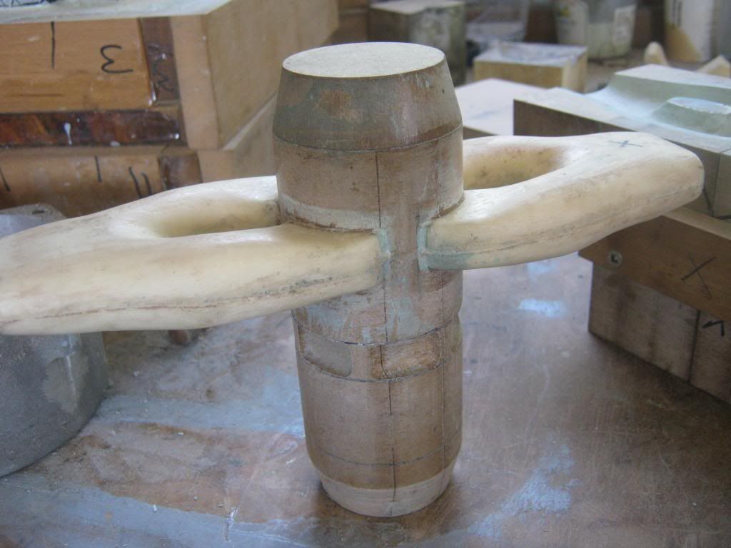
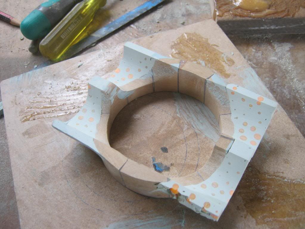
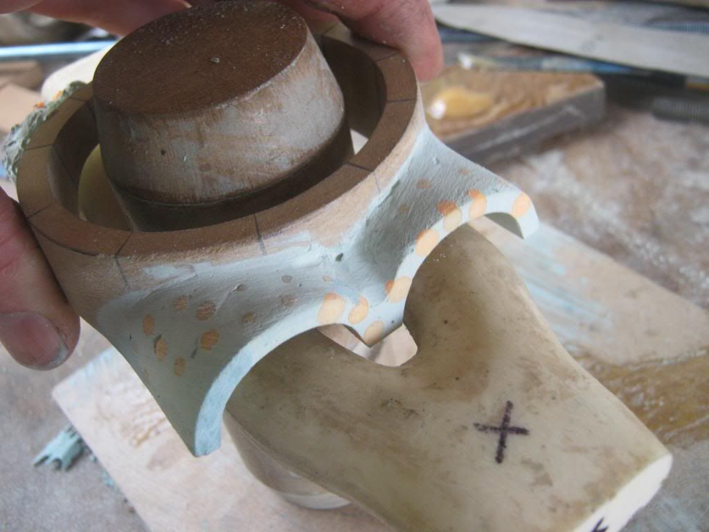
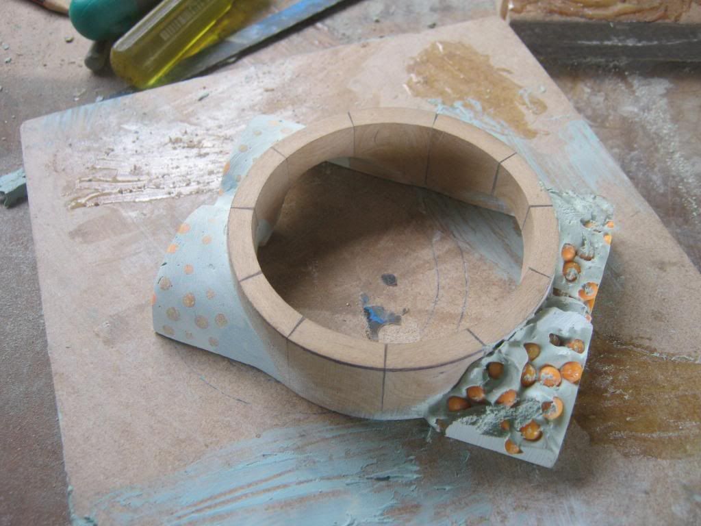
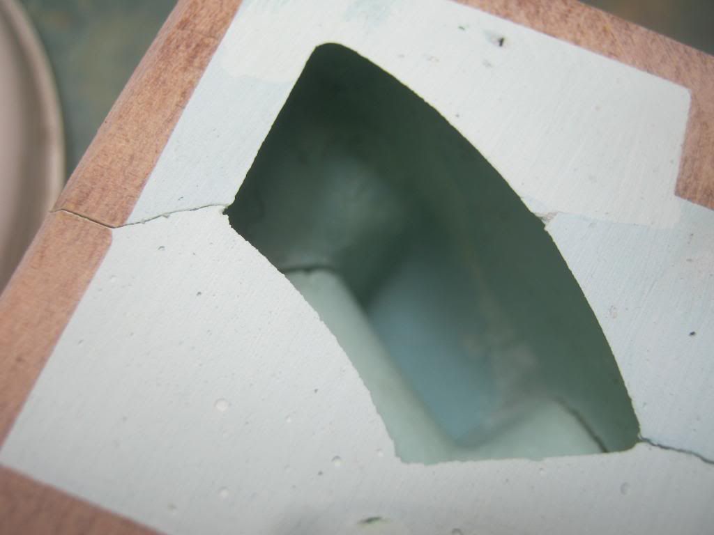
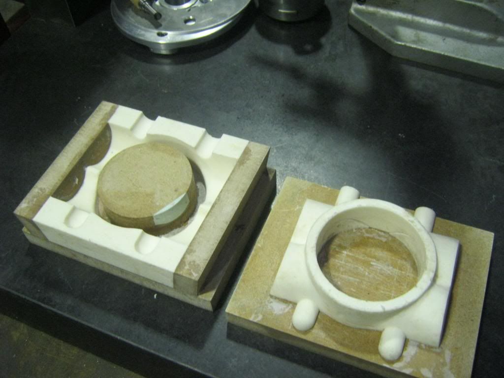
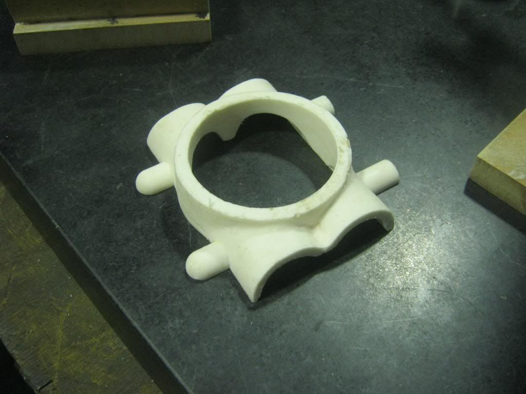
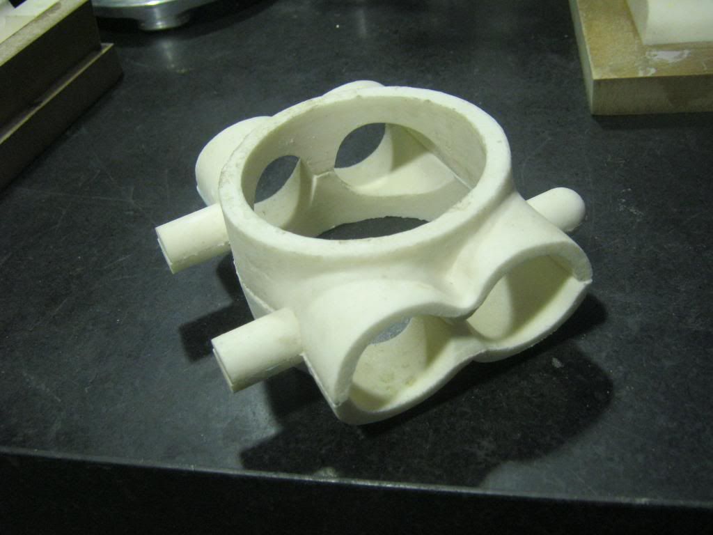
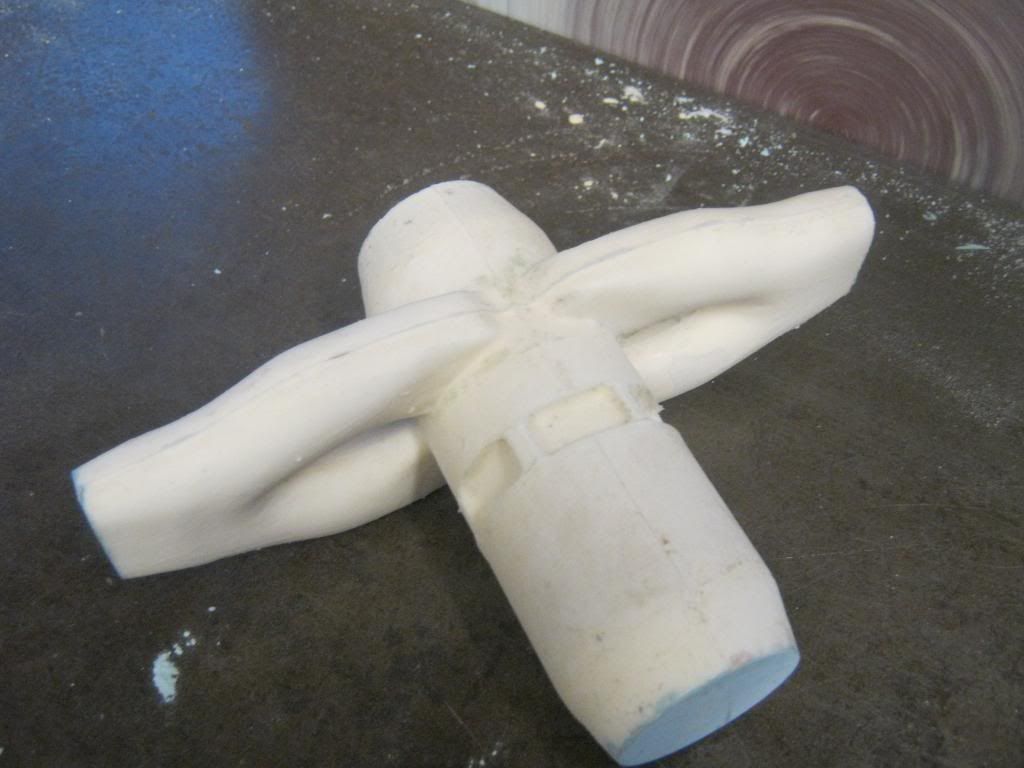
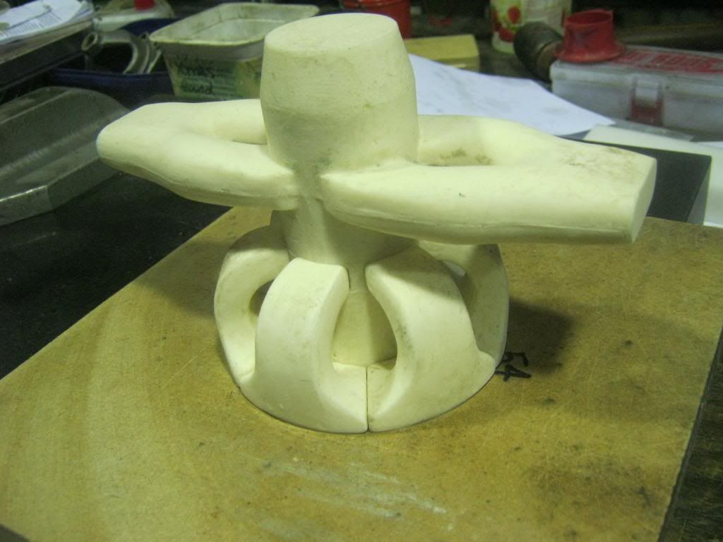
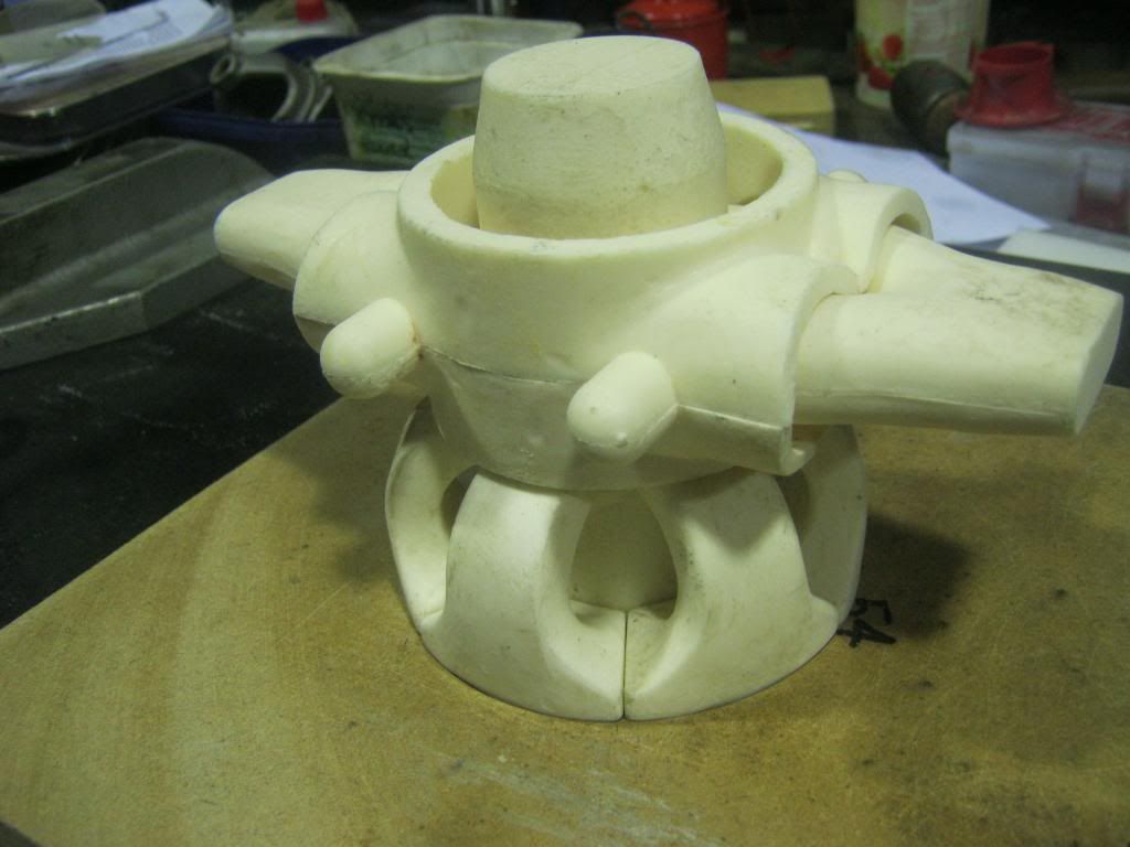
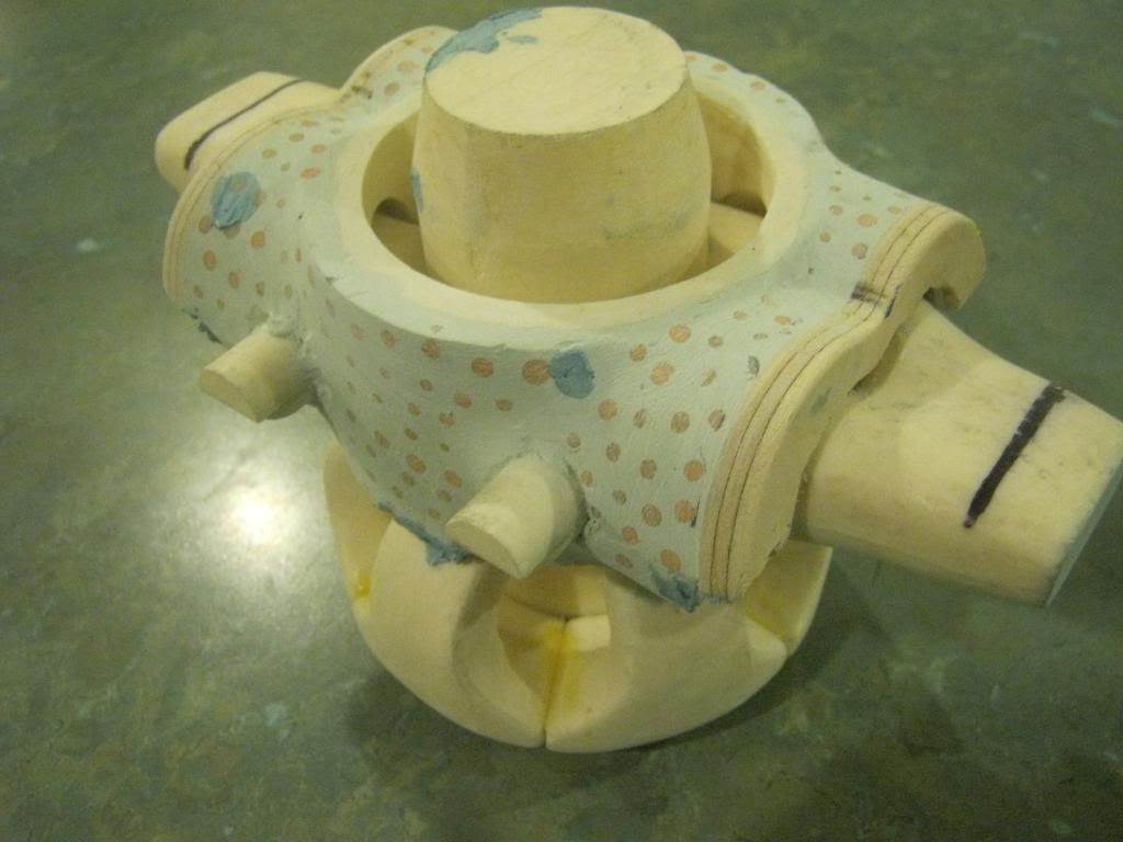
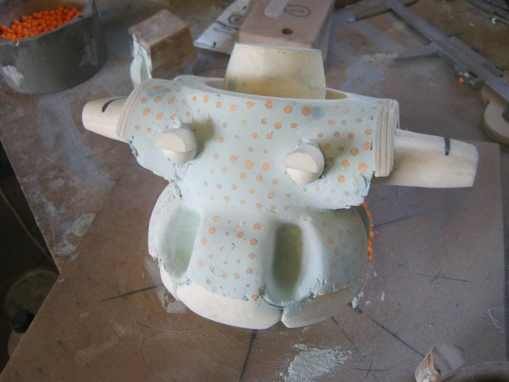
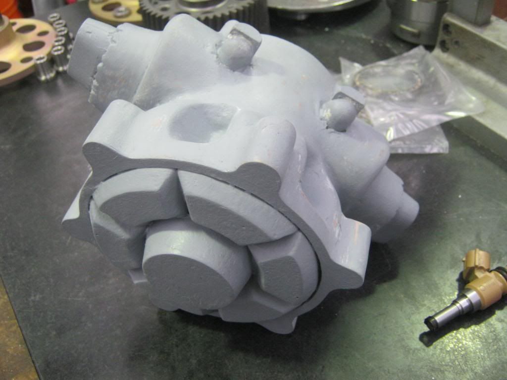
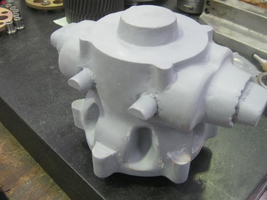
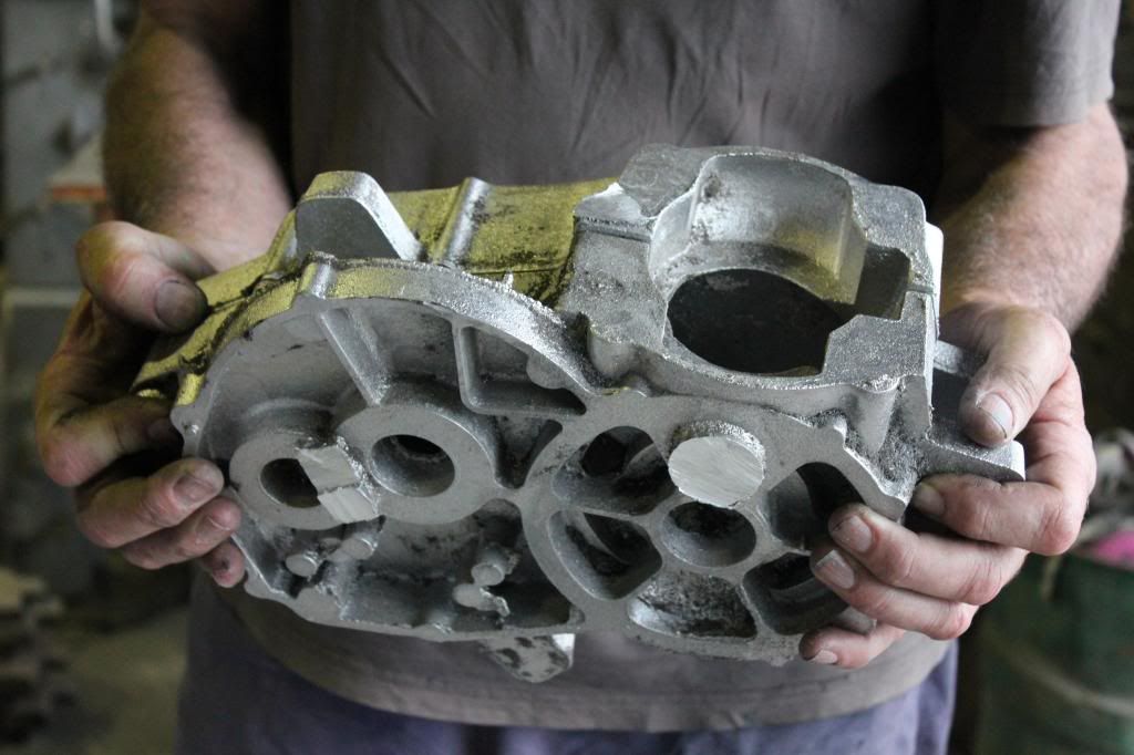
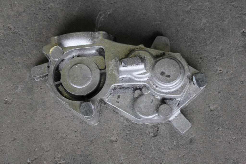
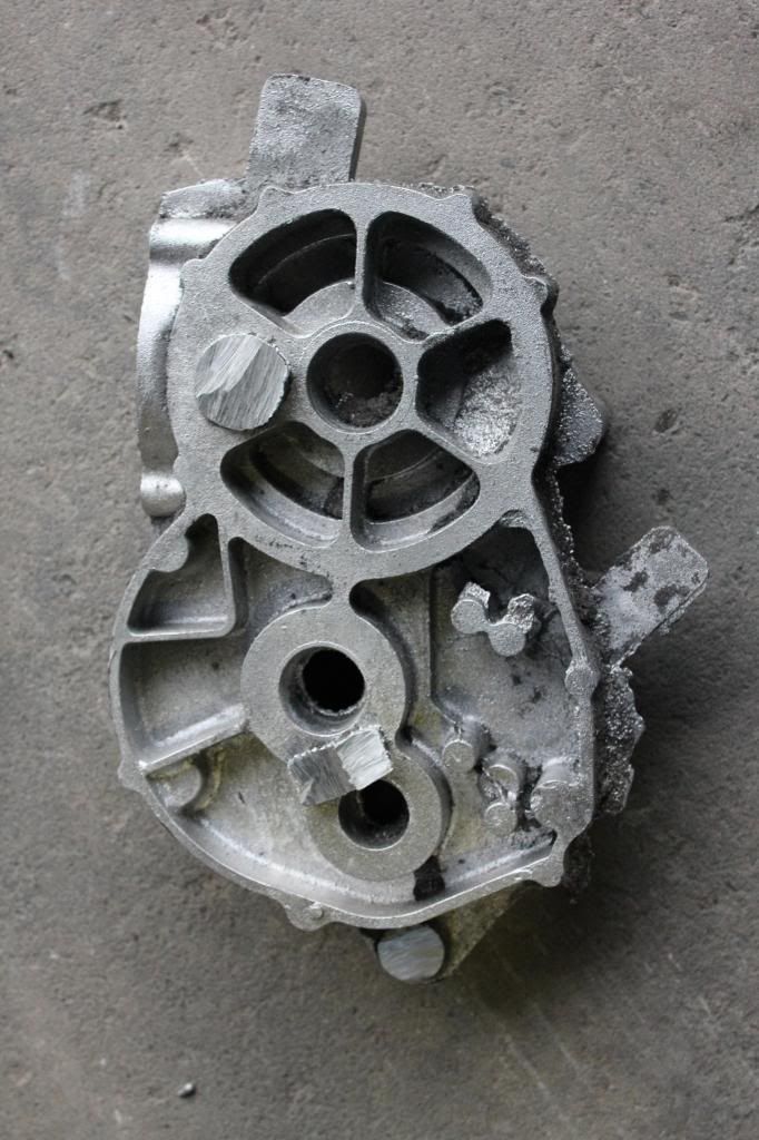
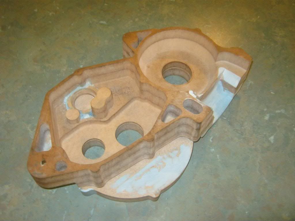
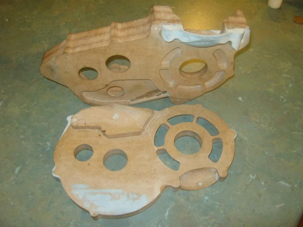
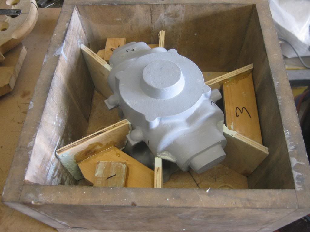
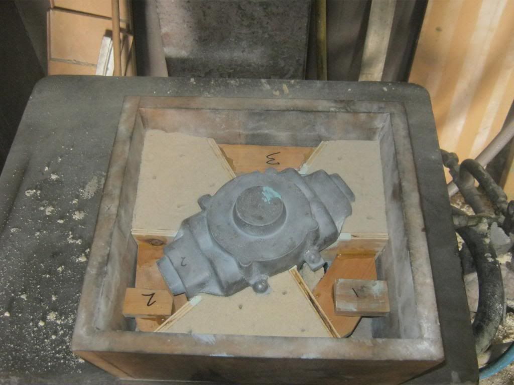
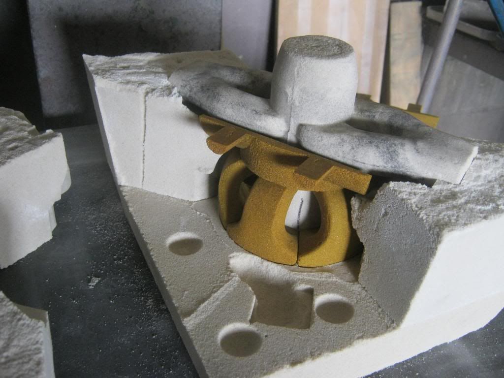
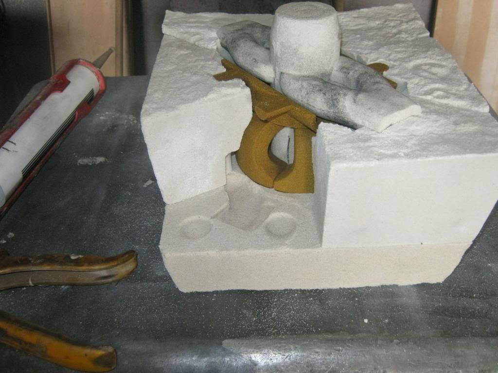
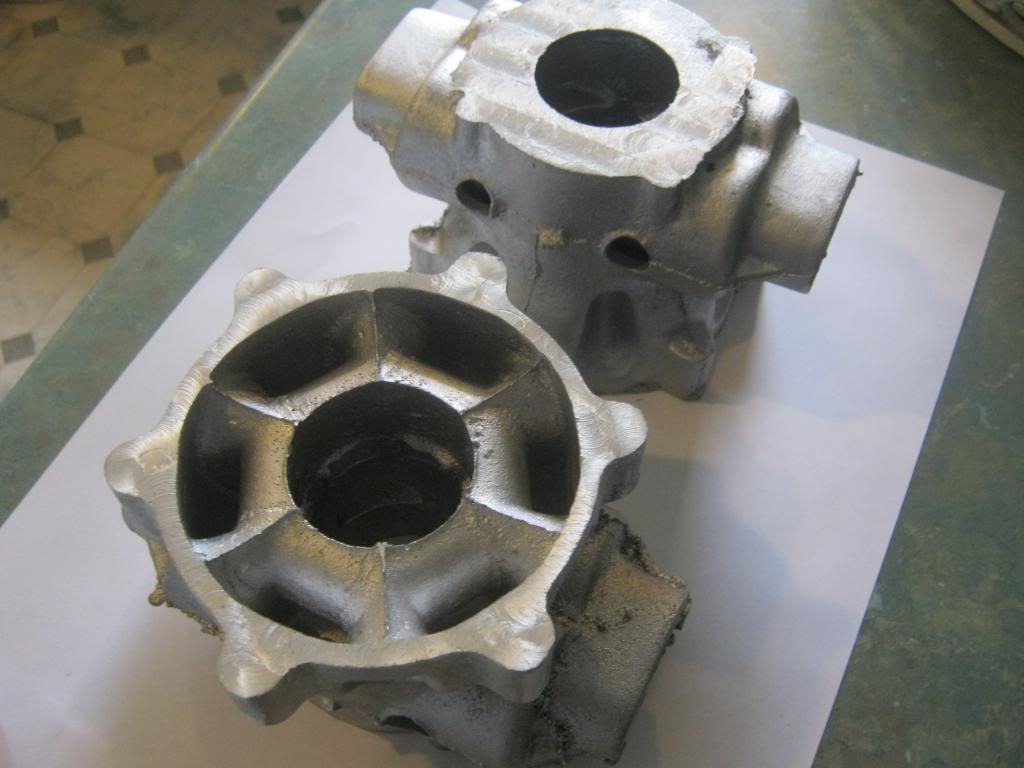
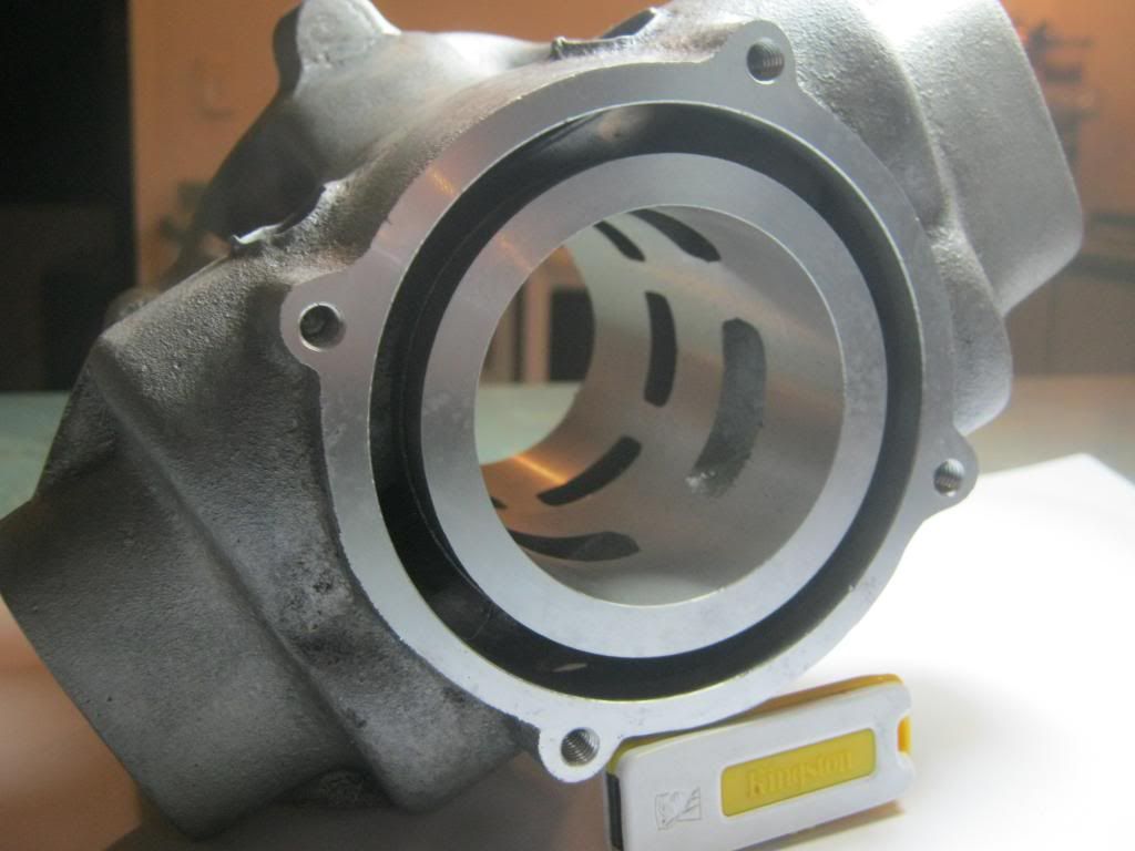
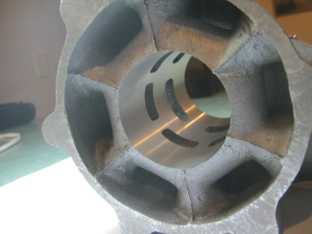
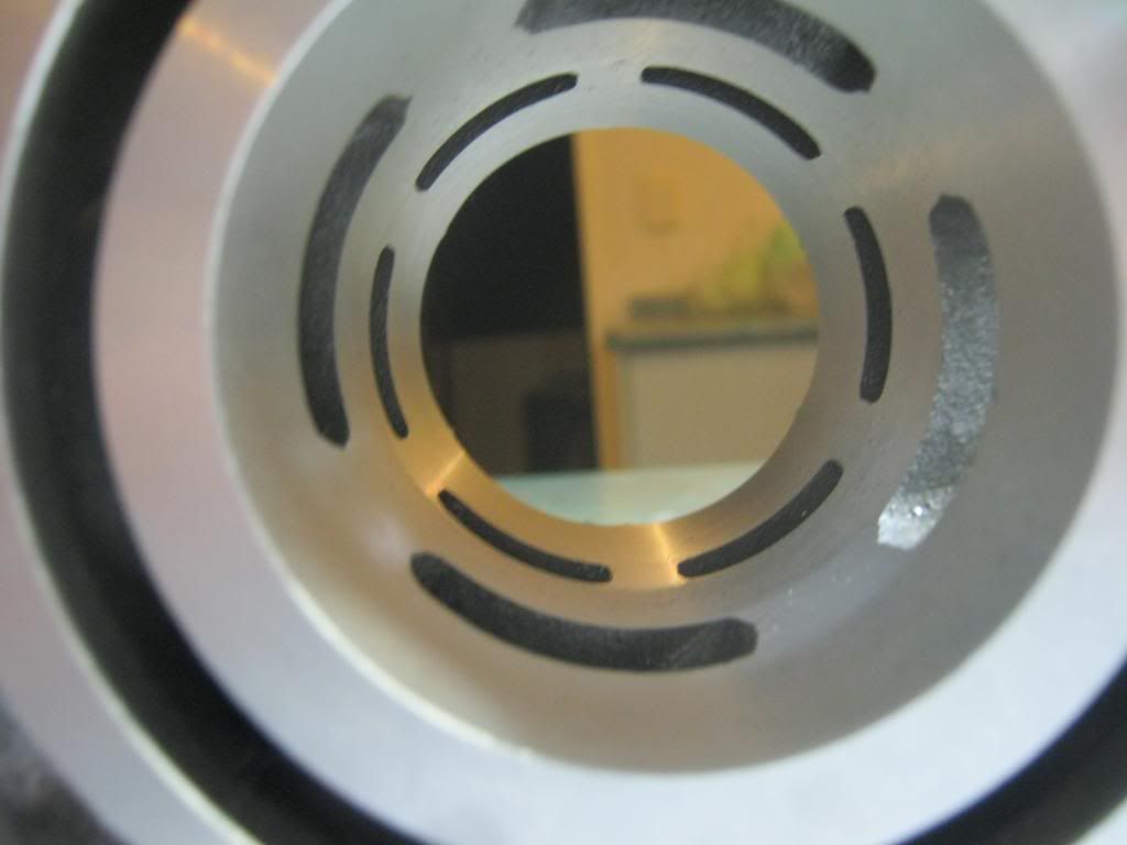
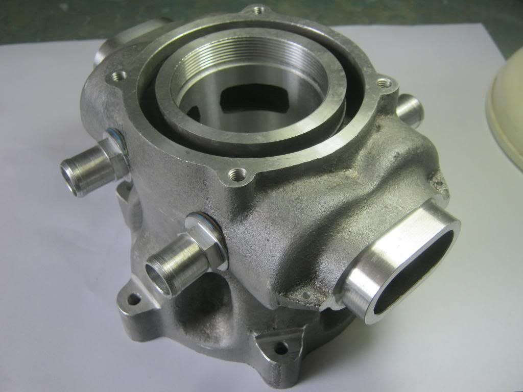
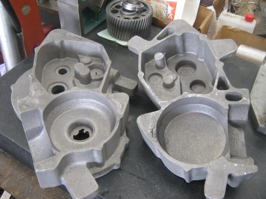
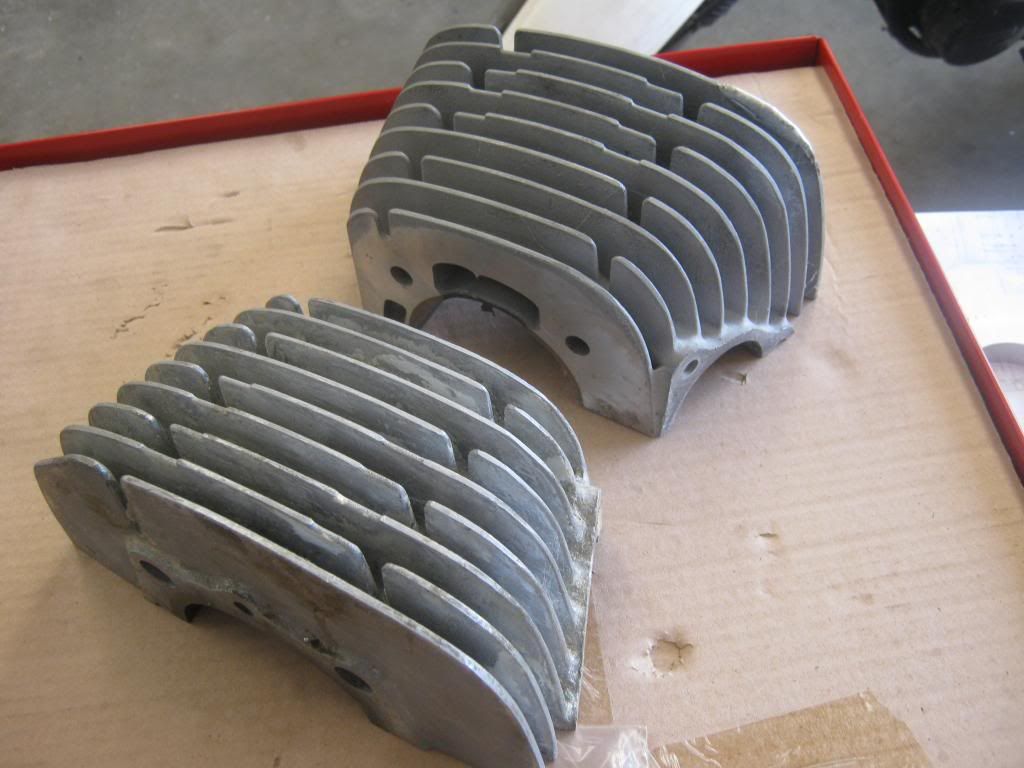
Neil, would it be possible to show a couple more photos of the pattern of the 360 cases (maybe I missed them, I'll go back and look). Love the water pump configuration, being an integergral part of the crank assembility rather than an after thought on the side.
Forum whore
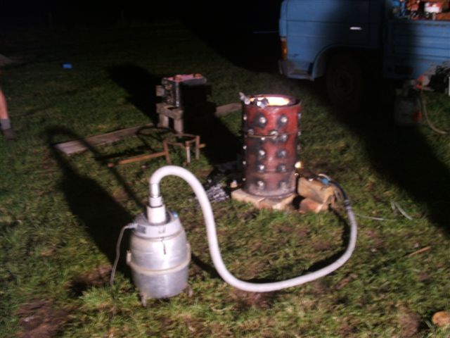
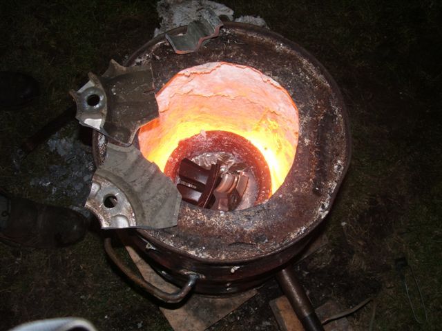
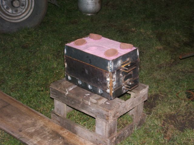
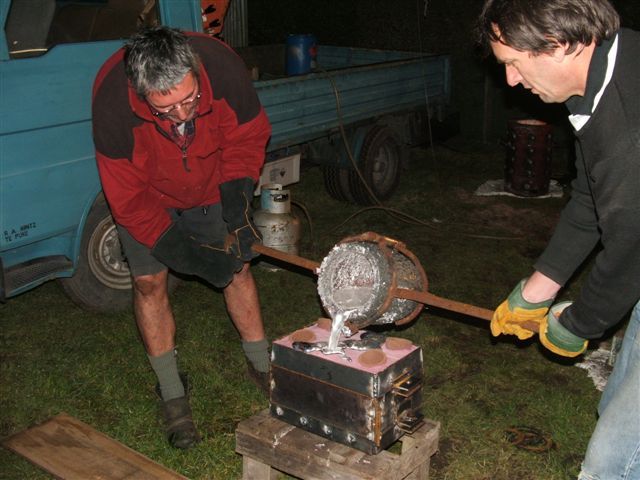
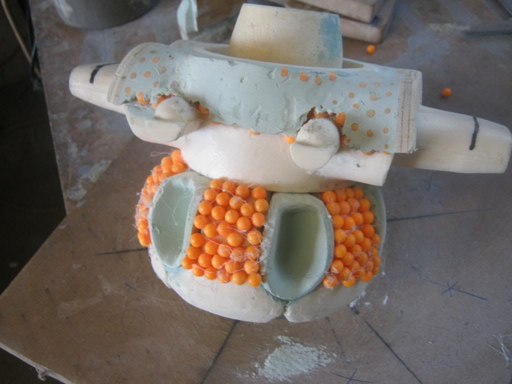
All this foundry stuff is great, here is some more from Aus its car stuff but pretty interesting all the same
http://www.dmdaustralia.com.au/block.html
My neighbours diary says I have boundary issues
Forum whore

Yep .....
Forum whore
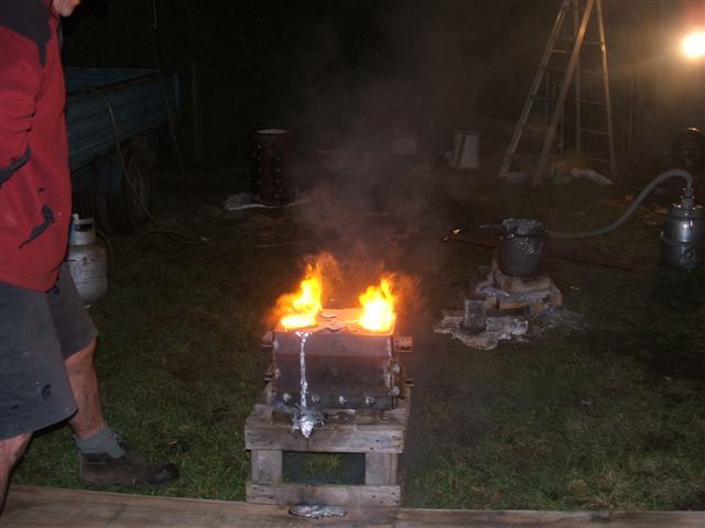
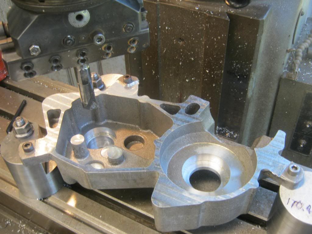
Tonights efforts.
Red line is my best with a carb on this cylinder, Blue line is where I am at now with the EFI.
There must have been some software setting I was getting wrong.
I am not sure what happened, but for a couple of weeks we have been struggling with the map table and trying to get it to run well and all the time the Beast has been a fussy pig.
Not knowing what good looked like I struggled on with a bad setup.
In desperation I switched the second injector off in the software and the engine started to run realy good, not at all fussy and easy to change the map and best of all I could instantly go to WOT at 4kish and it would pull away without fuss until it ran out of injector time around 12.
Although the secondary injectors were switched off they still showed up on the gauges, no doubt the problem was something simple, I am sure Matt from Ecotrons will put me straight.
I was close to giving up, but once the Beast started to run and I saw how easy it was to make changes with the map table I have to say I am getting excited about EFI again.
Forum whore
Way to go Neil.
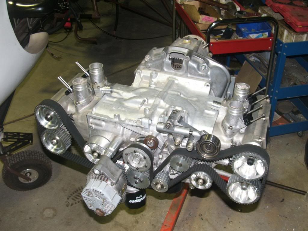
How are you going to accomplish that? Teethed Belt?Reverse cylinder and crank rotation.
Forum whore
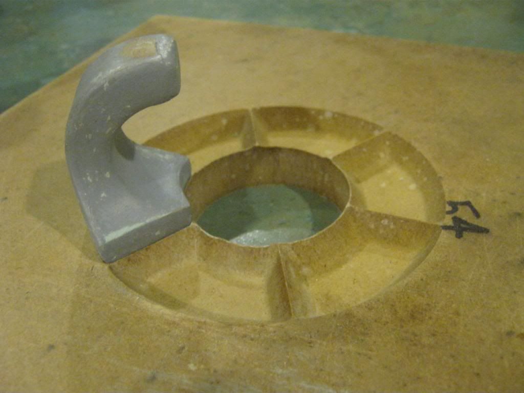
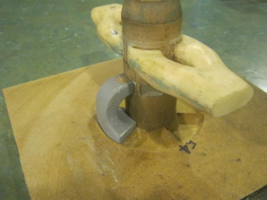
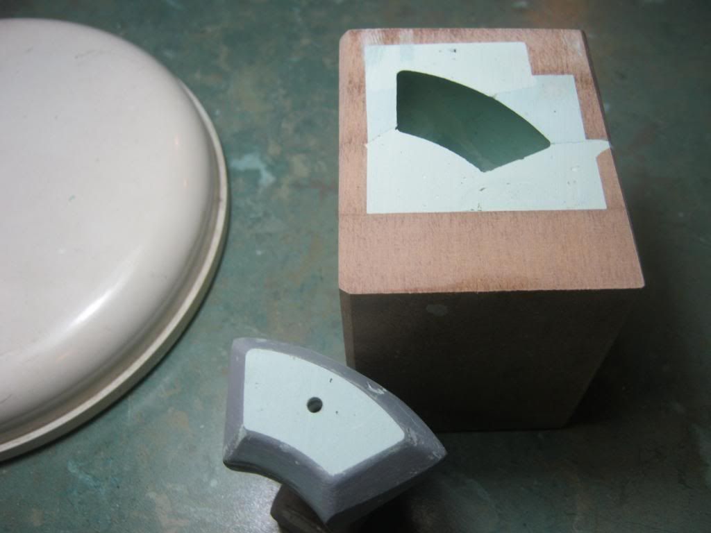
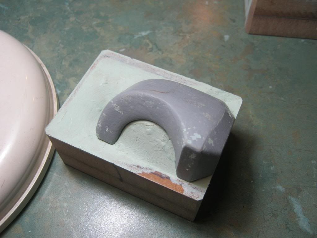
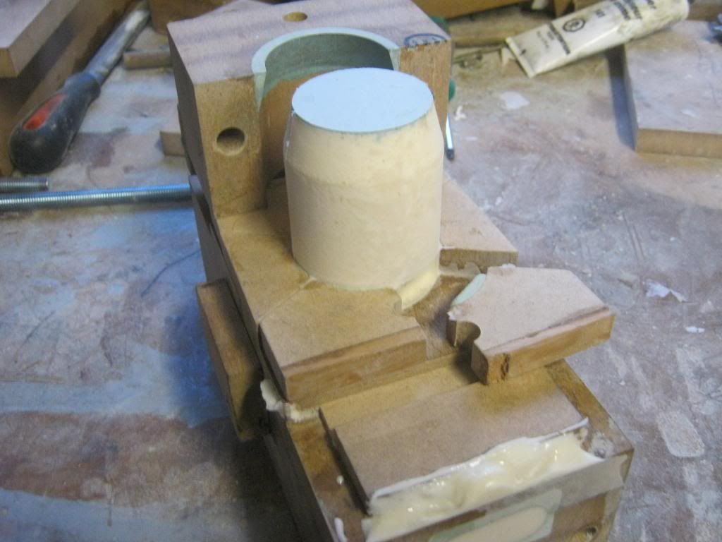
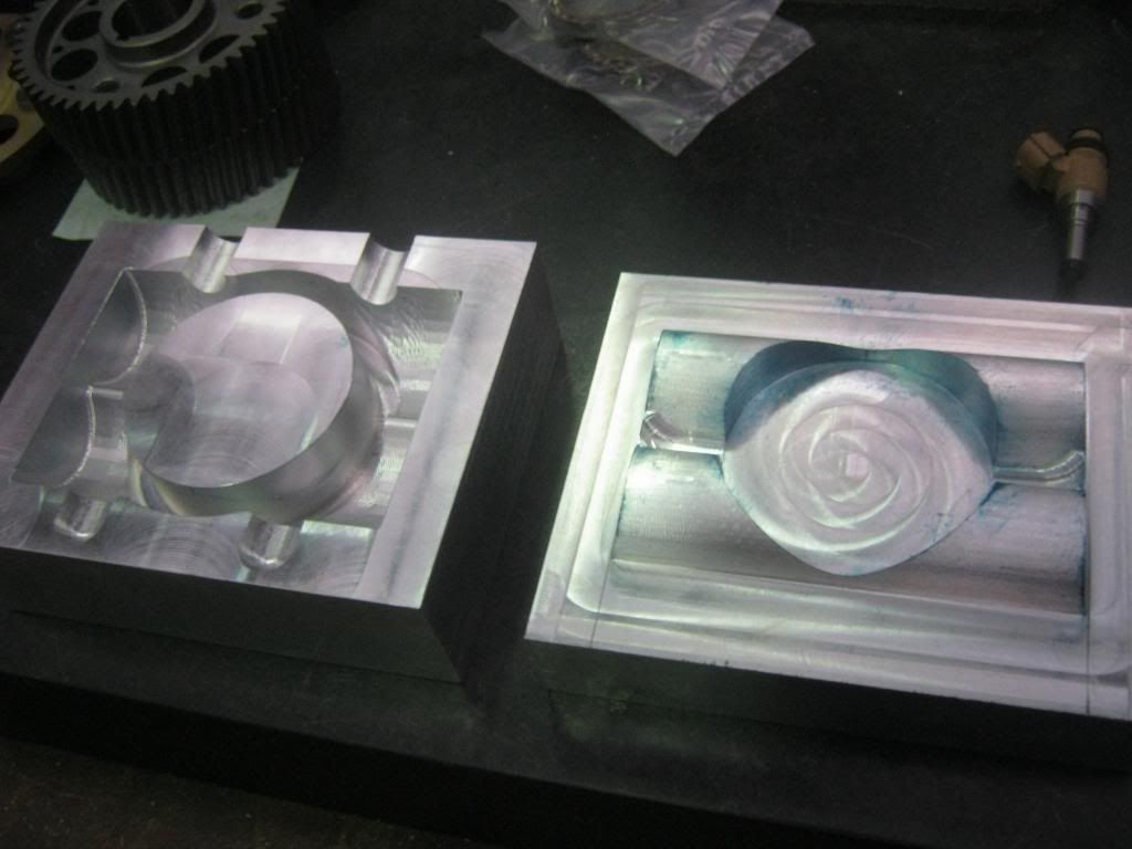
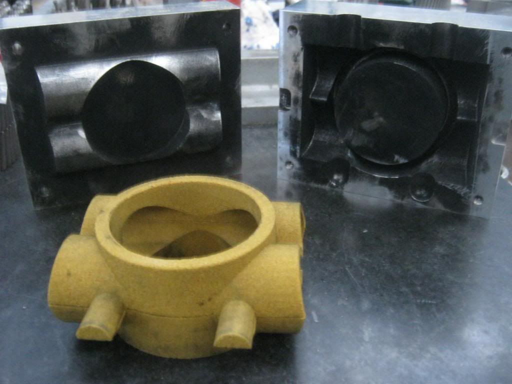
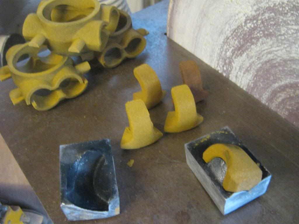
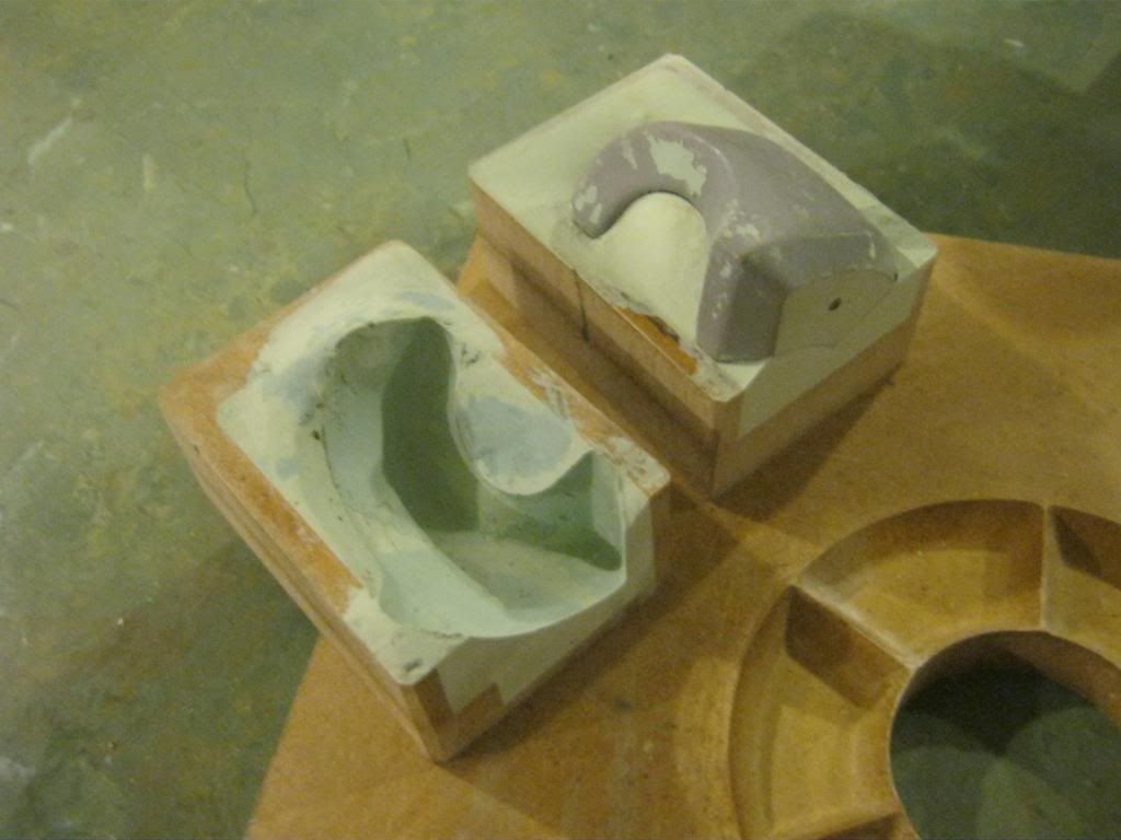
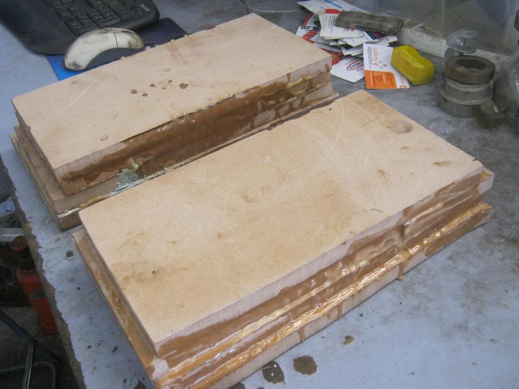
Patterns milled out on the CNC.
Reverse is via counter shaft ( gear drive ) also doubles as the ballance shaft.
Rob, Don't give up, it's the pain we all have to go through.
Anorak
Neil the Honda NSR125 Balance shaft set up is real neat.
Design lends itself to a real neat idler shaft

Kinky is using a feather. Perverted is using the whole chicken
Forum whore
A balance shaft is always a good idea, but putting your total power through the balance shaft's gear drive will lose you an unnecessary 5% of that total power
(which will heat up the cases, which will lose you still more power). And there is no need to run the crankshaft backwards because of your reversed cylinder.
Forum whore
It depresses me to think it took two weeks to twig to this but :-
I think I have fallen into a trap made by computer geeks.
Where in the virtual world of computer programing the logical numbering system starts at 0 not 1 like in the world of real things.
Its like this because in the real world you can have nothing and 0 means nothing but in the computer world an array position always contains something even if its nothing ......so 0 means the first position in a single dimension array, 1 is the second position and 2 is the third.
0,0 is the first position in a two dimensional array while 0,1 is the position next door and 1,0 is the other neighboring position to 0,0 and 1,1 is above 0,0 and between 1,0 and 0,1, nerd talk but you get the picture.
Apparently Ecotrons allows for 3 injectors per cylinder.
And I am beginning to think you can see the first one in the main screen and the other two labelled injector 1 and injector 2 in the advanced calibrations screen.
It is starting to look like.
0 = injector 1 on the main screen or the first logical item in a 1 dimensional array of three elements
1 = injector 1 in the advanced calibration screen or the second logical item
2 = injector 2 in the advanced calibration screen for the third logical item
Geek World ... Real World
0 = 1
1 = 2
2 = 3
so
0 = real Injector 1
1 = real Injector 2
2 = real Injector 3
Its simple really ......
So now I think I may have been confusing "logical" injector 1 with "real" injector 1, maybe logical injector 1 is actually real injector 2.
If this is the case it would explain the problems I have been having.
I have emailed Ecotrons support for clarification.
If that is not the answer, I will just have to fall back on my refined problem solving skills.
Will let you know.
Weekend cruiser

There are only 10 kinds of people in the world.
Those that understand binary notation, and those that don't !!!
Forum whore
10 binary = 2 real ......
Weekend cruiser

It's very easy to remember
10 to the base 2 = 2 to the base 10
Forum whore
Frits, somtimes a balance shaft is a necessity, I would be frightened to even get off the ground with this engine before the balance shaft was fitted, now I'd be happy to fly all day.
L-Plate Rider
Great dyno session on the FXR/FZR tonight. Mikuni TM33, Ross racing Piston and Kelford cams. Still a rough spot at 7000rpm, but likely to be exhaust length. 71 runs on the Dyno with a very patient Rob.
There are currently 32 users browsing this thread. (0 members and 32 guests)
 Posting Permissions

 Reply With Quote


Bookmarks