Yes a bucket for a Bucket. The front number board is the off cut from the bucket tail piece.Originally Posted by F5 Dave


 Forum whore

Yes a bucket for a Bucket. The front number board is the off cut from the bucket tail piece.
Forum whore

I tried to post a little technical story here to help you through the Christmas days, but I could not manage to insert the pictures the way I wanted to...
But in case you're curious, you might want to take a look here: http://www.pit-lane.biz/t3173p657-gp...-part-2#134197
Anorak
Here is a little technical story for the coming Christmas days. Its official title is Transfer Theory, but I call it
The leaning tower of Pisa
Transfer theory part 1
the central column
We want ample angle.area for our transfer ports while at the same time keeping their height within limits, so we need all the transfer area we can get; we want to use as much as possible of the cylinder circumference.
The best way to utilize the available real estate would be to aim all transfers radially inward; that way the cross section widths of all ports would be equal to their chord widths and you can't get any better than that. All transfer streams would meet in the center of the cylinder, slow each other down and form a central column with only one direction to go: upwards, in the direction of the cylinder head.
But since you can't have a transfer port at the exhaust side of the cylinder, an imbalance would occur and that central column would be inclined (sic) to topple over towards the exhaust side of the cylinder. You don't want that because too much of the fresh charge would take the escape route into the exhaust duct without first scavenging the cylinder.
How do you prevent that central column from leaning towards the exhaust side? If you omit the transfer ports directly opposite the exhaust, you would restore the scavenging balance, but you would sacrifice too much valuable port area. There is a solution, but let me address some other scavenging aspects first.
We want as much transfer port area as possible, so it would make sense to have all transfer ducts enter the cylinder perpendicularly, right? Nope.
To begin with, most pistons are domed, so transfer flow entering the cylinder would collide with the dome. Aiming the transfer ducts axially at about the same angle as the piston dome, usually about 10°, will not cost any effective cross section area and it will noticeably improve the flow coefficient. Larger-than-zero axial angles at the port floors will also enable you to fit larger inner radii in the transfer ducts, another benefit for the flow.
Second: those transfer streams entering the cylinder and colliding in the center will convert kinetic energy into potential energy. In English: their flow velocities will slow each other down in the collision process and the static pressure in the middle of the resulting central column will be higher than the pressure in the transfer ducts.
That static pressure in the central column is a good thing: it will provide for a higher density of the fresh charge in the column and that helps to expel the hot, thin burnt gases from the previous combustion cycle. Think of it as using a jet of water to chase away smoke: that will work a lot better than the other way around (using smoke to chase away the water).
But the static pressure at the foot of the central column can also have adverse effects. Too high a static pressure will impair the flow, because the higher this pressure is, the smaller will be the pressure differential that accelerates the charge through the transfer ducts. Aiming the transfer ducts axially a little will improve the flow, just like it did because of the domed piston. Slightly axially-aimed transfer streams will provide for a less violent, not completely head-on collision. The central pressure can be controlled this way, and the transfer streams will keep the axial component of their velocity, so the central column does not need to begin its journey to the cylinder head with zero velocity. So the axial column speed can be controlled as well by the axial transfer angles.
Transfer theory part 2
positional & directional scavenging angles
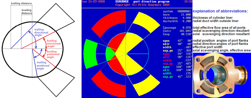
Most two-stroke people define radial scavenging directions by quoting the distances where the ports would intersect the center line (the leading distance and trailing distance in the drawing below left). Gordon Blair used that notation in his publications, and 95% of us followed suit.
But there is a better, more universally applicable way.
I will explain with an example, not of scavenging directions but of port timing: I might say that a transfer port height of 13 mm is perfect for a racing engine. That may be true for a 125 cc engine but it would be nonsense for a 50 cc or a 500 cc.
But if I say that a transfer port timing of 130° is perfect for a racing engine, then that is valid for any engine, regardless of its cubic capacity. Absolute distance values (millimeters, inches etc.) are not suitable for universal guidelines. Degrees are, as are percentages of bore or stroke. Rpm values are not; mean piston velocities are.
I express transfer duct directions in degrees. Each duct has a leading flank and a trailing flank. Each flank intersects the bore at a point which I can define with a positional angle. And each flank hits the fore-aft center line of the bore with an included angle which I call the directional angle. The drawing below left may clarify what I mean. And the drawing on the right is an example of an existing cylinder.
Now we can express the radial characteristics of the transfer ports with positional and directional angles, regardless of bore and stroke.
And we can express the ports' axial characteristics with axial angles, but that only gives a 'universal value' for engines with identical bore/stroke-ratios.
We may quote a height H in the cylinder where the transfer port's roof would hit the opposite cylinder wall. But we need to express H as a percentage of the stroke. Then we will have a truly universal value.
Then we will also see that short-stroke engines require smaller axial angles.
Transfer theory part 3
the tower of Pisa
As we are on the subject of scavenging angles, now would be a good time to say something about the axial angles of the A-transfers.
Surely a duct with an axial angle of over 20° offers a smaller cross-section to the flow than a duct that enters the cylinder perpendicularly?
Yes it does. But there are two good reasons to angle it upward anyway.
First, perpendicular mixture streams coming from the A-ports would collide and slow one another right down. The axial angles provide for less velocity losses and less pressure losses, so despite their smaller cross-section, upward ports may flow as much, if not more, than perpendicular ports.
(Now you may well ask why the B-ports do not get the same treatment. It is because the central scavenging column, resulting from all incoming scavenging streams together, must not have too much axial velocity, or the loop scavenging will result in a loop-loss into the exhaust).
Second, there is a thing called scavenging balance (I invented the word for my personal use, so this may well be the first time you ever saw it).
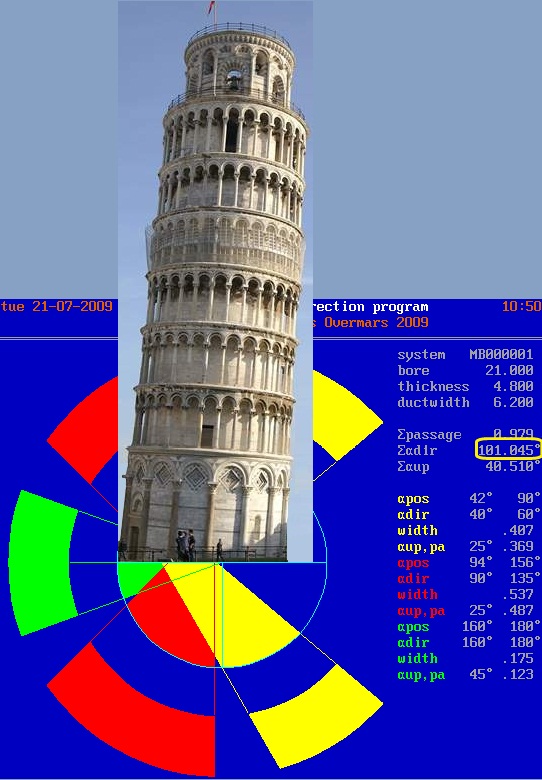
If you looked closely at the scavenging picture of the MB-cylinder I posted above, you may have noticed that the 'radial scavenging directional resultant' had a value of 101,045°.
90° would have meant 'straight up'; more than 90° indicates that the central scavenging column is leaning towards the exhaust side of the cylinder.
But we don't want that; it is bad for the scavenging of the rear part of the cylinder, and it is risky because it may provoke scavenging losses straight into the exhaust.
But how can we prevent a scavenging column from toppling over to the exhaust side like the leaning tower of Pisa? Not by pushing against its basis, but by pushing higher up. Hence the axial angle of the A-ports. The pictures will tell the story. (If only the Pisa architect had known a bit more about two-stroke scavenging....)
Transfer theory part 4
vectors
Let us assume that all transfer ports are of the same height. Let's also assume that a port with twice the cross-sectional width will give twice as strong an impulse (that is already doubtful; it presumes equal densities and equal flow velocities in all ducts, and as duct contents can have different inertias, their accelerations may differ, as will their flow velocities at any given moment).
If you accept these assumptions, you can resolve each transfer stream into an axial component, a fore-aft component over the piston, and a left-to-right component over the piston. The axial components all work in the same direction: towards the cylinder head. The left-to-right components will cancel each other out (if they don't the scavenging is asymmetric) while contributing to the pressure creation at the root of the central column (which in turn will accelerate the axial flow and thus enhance the axial vector), and the fore-aft components will result in a vector that may either point towards the rear side of the cylinder, be zero, or point towards the exhaust side.
This fore-aft vector together with the axial vector will give a resultant that will lean towards the rear of the cylinder, or point straight up towards the head, or lean towards the exhaust side.
What we want to achieve, is an axial column that clings to the rear of the cylinder, so it can wash away the spent gases with as little turbulence as possible. Turbulence will result in mixing of fresh charge and burnt gases, and we don't need that. And mixing will heat up the fresh charge, bringing it nearer to the detonation treshold. And we certainly don't need that!
I realize this is a crude way of describing a complicated flow dynamics event, but hopefully it will help you form a mental picture (no pun intended).Merry Christmas and a Happy New Year

Kinky is using a feather. Perverted is using the whole chicken
Forum whore
CVT Scooters with 16" wheels
Does what make and model of scooter that has 16" wheels????
Hardcore Biker
 Forum whore
Thanks Wax
If thats a 16" high profile road tyre, whats the bet a modified rim with a low profile racing 17" slick will fit in there.
Hardcore Biker
Your welcome. The downside is that your now swinging the whole engine as the swingarm and you have that unsprung weight to deal with
Forum whore
arg, its never easy .......
Anorak
Suzuki Burgman has largish wheels if you are into that kind of thing.
Re the Frits post above if Frits hits reply with quote he will see what i did
my guess is your advanced options is not turned on? if not next to save is go advanced.
i used a Code to center the pics

To align the text option on the advanced panel selection.to re-size pics i use this
Mr Mentaltrousers showed me how as he was sick of my over sized pics so thanks Mr T.
Kinky is using a feather. Perverted is using the whole chicken
Race it don't store it !


That is a great result, Tim must be happy with that, did you have to play with jetting ?
Forum whore
No, just a basic play around to get a view of whats possible. Tim is going to tickle the cylinder to see what can be done with it.
Forum whore
anyone know why on the run down of my 2 stroke it likes niping up? what do l look for ..thanks
Forum whore
Husa pointed me towards some pictures of CVT racers on the Pit-Lane.biz site.
Looking at the picture of this CVT racer it looks like there is no reduction gear box and that the front chain sprocket is behind the rear CVT pully and that they rely on the big rear sprocket to get sufficent overall gear reduction.
Originaly I had thought of having the rear cvt pully driving a 3:1 reduction gear set but the big rear sprocket setup is much simpler. All I have to do is find a big enough rear CVT pully so I can have a low enough first gear for starting off.
Forum whore
This maybe the answer, or maybe not, food for thought anyway ....
Page 600 has quotes about this from Frits and Jan.
Bogeyman
Worth noting that any form of conical pulley/belt drive is far less efficient than chain/sprockets, and the more force there is on a small drive pulley the more power will be lost in belt distortion/deflection. So making the bulk of your reduction in chain at the back wheel makes sense, even if it looks weird.
Go soothingly on the grease mud, as there lurks the skid demon
There are currently 26 users browsing this thread. (0 members and 26 guests)
 Posting Permissions

 Reply With Quote
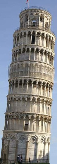
Bookmarks