Bet you cant wait for the royalties to start flooding inOriginally Posted by Flettner


 still basking in the glory..

Bet you cant wait for the royalties to start flooding in
Forum whore

There is something very wrong about the case volume in the AM6.
If its 305cc at TDC then the case ratio is 1.22 - that is HUGE ie it cant be right, or if it is then you will never be able to get it tuned correctly.
And the transfer ducts are ALWAYS included in the calculation of the total case volume at TDC.
E85 will react alot like Methanol in that a rich mixture wont loose power anything like petrol will, but of course it cools the pipe temp
alot more.
Ive got a thing thats unique and new.To prove it I'll have the last laugh on you.Cause instead of one head I got two.And you know two heads are better than one.
Moped rider

Confirmed here.
Oil pump looks like the same as the Aprilia ditech.
I wish I had the smarts/time to write 2 stroke specific firmware for my ecu. Oil pump output would be awesome.
Anorak

http://dirtbiketest.com/fresh-dirt/k...tkrrbkFy6Ob.97
KTM have patents so i guess we can search to see what their and Mikunis are in relation to it.
I guess if people ran vastly different petrol/oil mixture rates that the fuel injection might get a bit befuddled.
So the oil injection might be a work arround that.
I do hope the fuel injection is not as prone to low speed flame outs as the Four stroke equivilents are.

Kinky is using a feather. Perverted is using the whole chicken
L-Plate Rider
Thanks for the reply, wobbly !
Yes, the case volume may not be correct because of the way it was measured.
First the case was filled with cylinder attached without piston (yes, crankshaft and reed valve were also attached), then just se cylinder with piston fitted in TDC position with pin and needle bearing and filled with oil.
The case was filled untill the oil started reaching transfer ducts.
This way the connecting rod's volume is not included (so already at this point is not a true volume).
But I did not have many options..best would have been a drilled piston.
I got the 'idea' of too small exhaust duct / exhaust adapter, because the engine did not react any modifications like it previously did (higher peak bhp rpm).
The adapter is only 21,50mm ID..previous was something like 23....25mm.
Forum whore
No, they don't.
Anorak
I had a look for a Patent for KTM and i couldn't find it, but here a a few that stould out some are transfer injection other are intersting.
Interstingly IHI (as in the baby turbos the CX500 had as well as the Kei class cars)has a heck of a lot for uniflow two strokes.
Fuel injection system for a two-stroke engine
Publication number: 20020011223
Abstract: An internal combustion, two stroke engine is disclosed. The engine includes a crankcase with a cylinder adapted to house a piston. At least one transfer duct communicates the crankcase to the cylinder. At least one fuel injector is disposed through a wall of the transfer duct. The fuel injector is positioned to inject fuel tangentially to the cylinder.
Type: Application
Filed: July 18, 2001
Publication date: January 31, 2002
Inventors: Gunter Zauner, Michael Seyrl
Control system and method and engine control unit for internal combustion engine
Publication number: 20020020386
Abstract: There are provided a control system and method and an engine control unit for an internal combustion engine, which are capable of properly determining an amount of fuel to be injected during a two-stage fuel injection combustion mode and a duration period of this mode such that stable combustion and smooth transition between combustion modes are ensured, thereby attaining excellent drivability and fuel economy. The combustion mode of the engine is switched between a homogeneous combustion mode in which fuel injection into each cylinder is performed during an intake stroke, a stratified combustion mode in which the fuel injection into the cylinder is performed during a compression stroke, and the two-stage fuel injection combustion mode in which the fuel injection into the cylinder is performed once during the intake stroke and once during the compression stroke during transition between the homogeneous combustion mode and the stratified combustion mode.
Type: Application
Filed: August 10, 2001
Publication date: February 21, 2002
Applicant: Honda Giken Kogyo Kabushiki Kaisha
Inventors: Ken Ogawa, Toru Kimura, Yutaka Kohda, Kazuhiro Ueda
Fuel injection system for a two-stroke engine
Patent number: 6691649
Abstract: An internal combustion, two stroke engine is disclosed. The engine includes a crankcase with a cylinder adapted to house a piston. At least one transfer duct communicates the crankcase to the cylinder. At least one fuel injector is disposed through a wall of the transfer duct. The fuel injector is positioned to inject fuel tangentially to the cylinder.
Type: Grant
Filed: July 18, 2001
Date of Patent: February 17, 2004
Assignee: Bombardier-Rotax GmbH
Inventors: Günter Zauner, Michael Seyrl
Temperature-controlled fuel injection system for two-stroke engines
Publication number: 20060016434
Abstract: The present invention provides a system and method for controlling a two-stroke engine in correspondence with exhaust gas temperature. An engine control unit (ECU) receives an output from a temperature sensor mounted in the exhaust pipe. The engine control unit controls the operation of a fuel injector in fluid communication with the intake port of the engine in correspondence with the output from the temperature sensor. In one embodiment, correspondence is achieved by determining fuel injection parameters based on a plurality of maps, each corresponding to a different temperature range. The ECU references the map corresponding to the sensed temperature of the exhaust gas. Fuel injection parameters may include injection timing and the amount of fuel injected.
Type: Application
Filed: July 20, 2005
Publication date: January 26, 2006
Inventors: Daniel Johnson, Kim Chervestad, Greg Spaulding
Temperature-controlled fuel injection system for two-stroke engines
Patent number: 7258107
Abstract: The present invention provides a system and method for controlling a two-stroke engine in correspondence with exhaust gas temperature. An engine control unit (ECU) receives an output from a temperature sensor mounted in the exhaust pipe. The engine control unit controls the operation of a fuel injector in fluid communication with the intake port of the engine in correspondence with the output from the temperature sensor. In one embodiment, correspondence is achieved by determining fuel injection parameters based on a plurality of maps, each corresponding to a different temperature range. The ECU references the map corresponding to the sensed temperature of the exhaust gas. Fuel injection parameters may include injection timing and the amount of fuel injected.
Type: Grant
Filed: July 20, 2005
Date of Patent: August 21, 2007
Assignee: Arctic Cat Inc.
Inventors: Daniel J. Johnson, Kim Chervestad, Greg Spaulding
TWO-STROKE ENGINE WITH FUEL INJECTION
Publication number: 20150184574
Abstract: In a two-stroke engine including a scavenging port (43b) having an open end (42d) opening out in a side wall of the cylinder bore (3a) and communicating with a crank chamber (2a), the open end being configured to be closed and opened by the piston (22), a fuel injection device (71) is mounted on the engine main body so as to inject fuel onto a back side of the piston and/or a part of the side wall of the cylinder bore located under the piston via the open end of the scavenging port or via the open lower end of the cylinder bore. The fuel deposited on the surfaces of the piston and the cylinder inner wall promotes the cooling of such parts.
Type: Application
Filed: October 15, 2014
Publication date: July 2, 2015
Applicant: HONDA MOTOR CO., LTD.
Inventors: Yoshikazu Yamada, Mashu Kurata
Direct injection two stroke engine combustion mapping
Patent number: 6505600
Abstract: A control unit is provided for an internal combustion engine including an engine block comprising a plurality of cylinders operable in a homogenous combustion mode and a stratified combustion mode in response to an engine throttle position. The control unit is programmed to switch the engine cylinders to the homogenous combustion mode at a throttle position of greater than about 20% of wide open throttle. As such, the combustion mode is switched form the stratified combustion mode to the homogenous combustion mode at a higher throttle opening that more capably supports increased fuel injection quantities of homogenous combustion in the engine cylinders. Problematic conditions of conventional pontoon boat systems due to switching of engine cylinders to homogenous combustion at high RPMs and restricted throttle openings is therefore avoided.
Type: Grant
Filed: November 6, 2000
Date of Patent: January 14, 2003
Assignee: Bombardier Motor Corporation of America
Inventor: Patrick C. Tetzlaff
ENGINE START CONTROL SYSTEM AND METHOD
Publication number: 20100250105
Abstract: A 720-degree motor stage storage means for holding the result of stroke discrimination for the engine E also in the period for carrying out an idle stop control is provided. At the time of restarting the engine E from an idle stop state, a new stroke discriminating processing is not conducted, but the result of stroke discrimination stored in the 720-degree motor stage storage means is used, to thereby drive a fuel injection system and an ignition device. A stage decision unit for allocating a period of two revolutions of a crankshaft to 720-degree motor stages based on the result of stroke discrimination, a fuel injection and ignition stage correlation table having predetermined correlations of 720-degree motor stages with fuel injection stages and ignition stages, and restarting time motor stage conversion means for conversion of a 720-degree motor stage into a fuel injection stage and an ignition stage, are provided.
Type: Application
Filed: March 10, 2010
Publication date: September 30, 2010
Applicant: HONDA MOTOR CO., LTD.
Inventors: Toshiya NAGATSUYU, Toshifumi OSAWA, Katsuhiro UTSUGI
TWO-STROKE INTERNAL COMBUSTION ENGINE
Publication number: 20120024275
Abstract: A two stroke crank case scavenged two-stroke internal combustion engine, the engine including: a cylinder (2) configured to reciprocatingly receive a piston (6) therein defining a combustion chamber (8), the combustion chamber comprising an ignition means (5) for igniting an air/fuel mixture and an exhaust port (40) for evacuating the exhaust fumes, a crank case (3) including a crank shaft (18), an indirect fuel supply system (4), such as a carburettor (12) or a low pressure fuel-injection system, for supplying fuel to the crank case (3) to be scavenged to the combustion chamber (8), at least one transfer duct (20, 20?) each extending from the crank case (3) to at least one corresponding transfer port (21, 21?) for connecting to the combustion chamber (8), additional air filling means (25, 24, 27, 23, 23?, 22, 22?,26, 26?) for at least partly filling the transfer duct/s (20, 20?) with additional air from the transfer port (21, 21?) towards the crank case (3), and a direct injection means (7) for injecting fue
Type: Application
Filed: March 31, 2009
Publication date: February 2, 2012
Applicant: HUSQVARNA AB
Inventors: Joel Berneklev, Mikael Bergman
Two-stroke engine and method for operating the same
Publication number: 20030209214
Abstract: A two-stroke engine (1) for a work apparatus includes a combustion chamber (3) configured in a cylinder (2). The engine includes a piston (5, 21) which drives a crankshaft (7) via a connecting rod (6). The crankshaft (7) is rotatably journalled in a crankcase (4). The two-stroke engine (1) includes at least three transfer channels (10, 11, 20) which connect the combustion chamber (3) to the crankcase (4) at pregiven control times. At pregiven control times, fuel is injected in the region of a transfer channel (10, 11, 20). A first component quantity of the fuel is transfer synchronously injected into the channel and a second component quantity from a preceding injecting cycle exits from the crankcase (4) into the combustion chamber (3). For this purpose, an injection nozzle (19) is mounted in at least one transfer channel (10). The injection nozzle (19) injects fuel into the transfer channel (10) open to the cylinder (2).
Type: Application
Filed: May 8, 2003
Publication date: November 13, 2003
Inventor: Heiko Rosskamp
Stratified air scavenging in two-stroke engine
Patent number: 4995349
Abstract: A two-cycle engine has an air inlet in the crankcase, and a spiral air-fuel passage encircling the cylinder wall rising from the crankcase to an inlet in the cylinder head to effect cooling of the cylinder. A fuel injection device introduces fuel into the transfer passage. A unidirectional valve admits air and fuel into the cylinder head and curved fins impart a swirling action to the air and fuel to effect a fuel and air stratification. An exhaust passage in the cylinder wall has an adjustable throttle to control dirctly the outflow of exhaust gases and indirectly the inflow of fresh fuel-air mixture, whereby the power level of the engine is controlled.
Type: Grant
Filed: August 7, 1989
Date of Patent: February 26, 1991
Assignee: Walbro Corporation
Inventor: Charles H. Tuckey
Two-stroke internal combustion engine
Patent number: 8677954
Abstract: A two stroke crank case scavenged two-stroke internal combustion engine, the engine including: a cylinder (2) configured to reciprocatingly receive a piston (6) therein defining a combustion chamber (8), the combustion chamber comprising an ignition means (5) for igniting an air/fuel mixture and an exhaust port (40) for evacuating the exhaust fumes, a crank case (3) including a crank shaft (18), an indirect fuel supply system (4), such as a carburettor (12) or a low pressure fuel-injection system, for supplying fuel to the crank case (3) to be scavenged to the combustion chamber (8), at least one transfer duct (20, 20?) each extending from the crank case (3) to at least one corresponding transfer port (21, 21?) for connecting to the combustion chamber (8), additional air filling means (25, 24, 27, 23, 23?, 22, 22?,26, 26?) for at least partly filling the transfer duct/s (20, 20?) with additional air from the transfer port (21, 21?) towards the crank case (3), and a direct injection means (7) for injecti
Type: Grant
Filed: March 31, 2009
Date of Patent: March 25, 2014
Assignee: Husqvarna AB
Inventors: Joel Berneklev, Mikael Bergman
Two-stroke engine and method for operating the same
Patent number: 6851402
Abstract: A two-stroke engine (1) for a work apparatus includes a combustion chamber (3) configured in a cylinder (2). The engine includes a piston (5, 21) which drives a crankshaft (7) via a connecting rod (6). The crankshaft (7) is rotatably journalled in a crankcase (4). The two-stroke engine (1) includes at least three transfer channels (10, 11, 20) which connect the combustion chamber (3) to the crankcase (4) at pregiven control times. At pregiven control times, fuel is injected in the region of a transfer channel (10, 11, 20). A first component quantity of the fuel is transfer synchronously injected into the channel and a second component quantity from a preceding injecting cycle exits from the crankcase (4) into the combustion chamber (3). For this purpose, an injection nozzle (19) is mounted in at least one transfer channel (10). The injection nozzle (19) injects fuel into the transfer channel (10) open to the cylinder (2).
Type: Grant
Filed: May 8, 2003
Date of Patent: February 8, 2005
Assignee: Andreas Stihl AG & Co. KG
Inventor: Heiko Rosskamp
Valveless two-stroke-cycle oscillating engine
Patent number: 5228414
Abstract: A two-stroke-cycle engine has a pivoted divider oscillating within a fan-shaped combustion volume. The divider is connected to a connecting rod which is connected to an output crankshaft. Seals are used instead of piston rings. Each of the two radial walls has a spark plug and a fuel injection tube located near the outer end. Each planar parallel side wall has an air inlet port near the inner end. An exhaust port is located in the center of the arcuate wall.
Type: Grant
Filed: September 10, 1992
Date of Patent: July 20, 1993
Assignee: Robert D. Hall
Inventor: Jimmye Crawford
Two-stroke engine and method of operating the same
Patent number: 6899067
Abstract: A two-stroke engine, especially for a portable handheld work apparatus, includes a combustion chamber configured in a cylinder. The combustion chamber is delimited by a piston which moves upwardly and downwardly. Combustion air is supplied to the engine via an air channel. The air channel opens with an air channel window into the cylinder. The crankcase of the two-stroke engine is connected at pregiven piston positions to the combustion chamber via transfer channels. The transfer channels open with inlet windows into the cylinder. An injection nozzle opens into at least one transfer channel. In the region of top dead center of the piston, the air channel is connected via a piston window to a transfer channel. An injection nozzle is arranged in the transfer channel and injects fuel into the transfer channel during the induction of combustion air into the crankcase.
Type: Grant
Filed: June 17, 2003
Date of Patent: May 31, 2005
Assignee: Andreas Stihl AG & Co. KG
Inventors: Heiko Rosskamp, Christian Puchas
Engine brake system of a two-cycle engine for a motor vehicle
Patent number: 4941441
Abstract: A two-stroke engine has a scavenge pump provided in an intake passage, a bypass around the scavenge pump and a fuel injector provided for injecting fuel in a cylinder of the engine. A valve is provided in the bypass so as to close the bypass. When deceleration of a vehicle is detected, the valve is closed and the fuel injection from the fuel injector is stopped.
Type: Grant
Filed: August 18, 1989
Date of Patent: July 17, 1990
Assignee: Fuji Jukogyo Kabushiki Kaisha
Inventor: Hideo Watanabe
Two-stroke, homogeneous charge, spark-ignition engine
Publication number: 20090056687
Abstract: A method for combusting fuel in an engine involving decreasing a first volume of air to a third volume, in two stages, the first stage in a crankcase compressor decreasing a first volume of air to a second volume and a second stage in the engine cylinder decreasing a second volume of a gas to a third volume, injection of fuel between the two stages into partially compressed hot air to provide homogenous charge to the cylinder to begin second stage compression in the cylinder having two variable compression ratios, a first variable compression ratio for low loads to reach a compression temperature slightly below the autoignition temperature of the homogeneous charge such that spark ignited HCCI-like combustion being emission free, a second much smaller variable compression ratio for preventing pre-ignition at high loads, then increasing the pressure at constant volume via combusting homogeneous charge in the cylinder, increasing the third volume of gas to a fourth volume (an expansion process having a chosen e
Type: Application
Filed: August 28, 2007
Publication date: March 5, 2009
Inventor: Pao C. Pien
Kinky is using a feather. Perverted is using the whole chicken
Forum whore
Juho, one problem may solve the other: that 21,5 mm adapter may provide you with a holed piston.
25 mm should be about the right adapter size.
Great thinking: if the EGT drops, you can correct it by leaning the fuel-air mixture.Temperature-controlled fuel injection system for two-stroke engines
Patent number: 7258107
Abstract: The present invention provides a system and method for controlling a two-stroke engine in correspondence with exhaust gas temperature.
Generally this will work. There's just one snag. When detonation sets in, the EGT will drop, so the Engine Control Unit will lean the mixture, stimulating more detonation. Don't try this at home.
Anorak
Aimed more at low bmep more non comp engines me thinks.
What did you think of this. (Very Honda)
ENGINE START CONTROL SYSTEM AND METHOD
Publication number: 20100250105
Kinky is using a feather. Perverted is using the whole chicken
Moped rider
I believe this is what the E-TEC snow mobiles do, but they have a knock sensor to detect detonation.
L-Plate Rider
Hi Juergen.
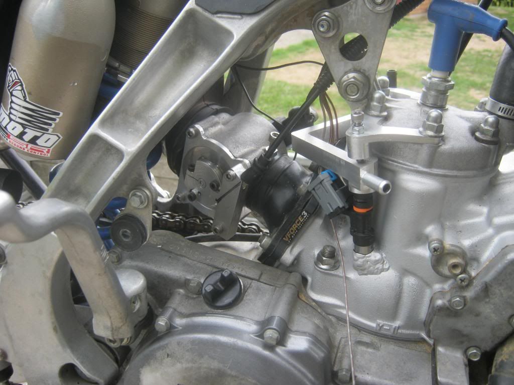
Jeah... I also like it a lot, turned out great. Martin sculptured it for me after we agreed on the design, ccs, etc.
Have you noticed it protrudes into th cyl. just like Jan spoke about a few pages ago?
And about the short circuiting caused by strangely designed piston that also came up a few pages ago.
Also encountered this problem with the Gasgas piston.
Decision was made not to open aux. exhaust pass the holed piston sides.
Engmod showed enough TA with 193* exh. duration. 72X72 are relatively big numbers, around 9500 rpm at max power with good overrev was the goal.
Forum whore
Very Honda indeed. Who else would write "720-degree motor" instead of 'foul-stroke'. Swankers! (you may omit the S if you so desire).
My first thought while reading it was 'hit or miss', soon followed by 'hit and miss'
L-Plate Rider
Alright, thank you !
The engine seems to not detonate, knock or blow up easily. Not sure why, but it has been ran on very high compression, extremely lean conditions.. but never overheated (water temp won't get over 60C -- not sure how it would change on dyno).
I forgot to mention one important problem: the piston.
It has 2 thick (1,20mm) rings and slots above piston pin (which connect aux exhaust ports and main transfer ports) !
I'm sure it will cause some problems..and power loss.
And yes, it's only a temporary solution, because previous single ring piston was worn out (piston ring end gap 0,70mm and piston-to-cylinder wall clearance more than 0,07mm)
Forum whore
That then is the problem with the AM6.
If you have holes in the skirt above the small end that connect the Aux and the A transfer,then it will run rich,and will not respond at all
to jet changes.
The seemingly rich mixture in the Exhaust is caused by the short circuiting, not by rich jetting, so you go leaner and nothing happens.
A file I have of a fully tuned TZR50 that puts out 18Hp Crank at 13,000 with triple Exhaust ports and this has a spigot exit area equivalent to 22mm.
This is 78% of the Exhaust effective area, and gives a Mach of 0.8 , absolutely fine.
Going slightly bigger in displacement or making more power than this would put the exit velocity close to sonic, so yes this may well be an issue as well.
The case com ratio is a very important element, guessing or not measuring it correctly isnt an option.
PS - you have a worn out piston available, drill a hole in it.
Ive got a thing thats unique and new.To prove it I'll have the last laugh on you.Cause instead of one head I got two.And you know two heads are better than one.
Moped rider
Casal-Fan,
Take a look at the KTM 300 piston, 18mm pin, 38mm compression Height(same as the GasGas), ring pins set at the 6:00 position. The cutout should not expose the exhaust/transfers on the cylinder pictured (GasGas EC300?)
Interested to hear more about your build/setup.
There are currently 23 users browsing this thread. (2 members and 21 guests)
 Posting Permissions


 Reply With Quote
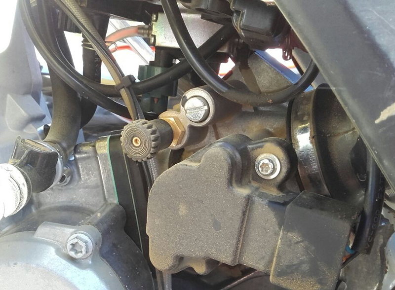
Bookmarks