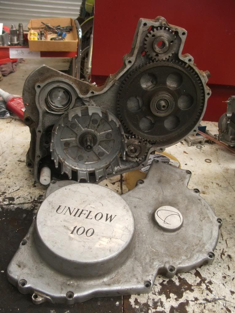
Been back to ESE head quarters this evening to balance my crankshaft. TeeZee set me up with some scales, some welding wire and a pile of washers. First up the rod, piston, pin and small end were weighed giving us a total of, I think 232gms, TZ works on the 50% theory so the wire and washers were weighed accordingly and hung off the end of the rod, this was then placed on the very technical looking balancing device where it was found to be PBC, the fly wheel was drilled in four places to get the correct balance.
Before all this we put it in the lathe and using a dial gauge we checked that it was running true, not too bad just a light tap with the truing device and we were happy.
Thanks to Tee Zee and Culley for their time.
If that last picture is the finished product it "looks" like it's balanced for about 2-3,000rpm. That's a lot of counterbalance. I would not be surprised if it vibrates like crazy from 5 up.
Actually the crankwheels aren't relieved inside much except right at the big end pin so probably not as bad as I first thought.
Last edited by speedpro; 7th February 2013 at 21:39.
Reason: had another look
First up the rod, piston, pin and small end were weighed giving us a total of, I think 232gms, TZ works on the 50% theory so the wire and washers were weighed accordingly and hung off the end of the rod, this was then placed on the very technical looking balancing device where it was found to be PBC, the fly wheel was drilled in four places to get the correct balance.
Let me start by complimenting you on a very clear description plus illustration of the balancing act. But you should not have drilled those holes where you did. As a rule of thumb, a good press fit requires that a big end pin hole should be surrounded by at least half its diameter in material. So for a 20 mm pin there should be at least 10 mm of crank web material everywhere around the hole. As you can see, the large original balancing holes already intrude into this zone, and with the small holes you added there will be little stiffness left.
Removing material in the blue circles would have been a safer approach, although it might not haved raised the balance factor sufficiently.
The best way would be to remove material from the inside faces of the crank webs, around the big end recesses. That would have two additional benefits: it would improve lubrication and cooling of the big end bearing and it would enlarge the crankcase volume.
Now that I am grumbling anyway: big end pins should be massive. The large void in the pictured pin is not exactly promoting a good press fit.
Tig weld the pin carfully to the crank, keeps the crank from twisting and the pin will most certenly stay in place,,, for ever
A very common mod on dragracebikes and snowmobiledragsters.
And make sure you have enough axial play at the big end of the rod before welding.
Do NOT go for the tight fit,, rather do a 'sloppy' one.
Keeps it from seizing at high revs.
you should not have drilled those holes where you did. As a rule of thumb, a good press fit requires that a big end pin hole should be surrounded by at least half its diameter in material. So for a 20 mm pin there should be at least 10 mm of crank web material everywhere around the hole. As you can see, the large original balancing holes already intrude into this zone
No doubt you have to work with what you have.
Maybe the pin could have expander plugs fitted like you see in the KT100 go cart engine to lock it in place.
A slug of Mallory Metal or Tungsten could be pressed into the flywheel opposite the big end pin instead of having to drill the extra balance holes so close to the pin.
Factual Facts are based on real Fact and Universal Truths. Alternative Facts by definition are not based on Truth.
In a moment of weakness I bought this cvt scooter, ticks a few boxes, cvt , 125 aircooled, $50, oozes style, lacks handling, just need to sneak it home
In a moment of weakness I bought this cvt scooter, ticks a few boxes, cvt , 125 aircooled, $50, oozes style, lacks handling, just need to sneak it home
I'll expect to see Brendon on it at Methven....you know you want to.....
Just so people get a handle on the reality of my situation re the F3 bikes.
One customer whos engine had done over 50 full noise dyno tests, took the bike to Taupo.
There it did 4 - 20 minute sessions as hard as it would go, bad front end issues, no brakes, and wrong gearing.
Max egt 1235 with 195/198 mains.
Pull the barrel and the pistons look like new - see the pic..
Now it has done another full day at Manfield with super rich jetting to try and nail the handling.No problems, needs attention at trailing part throttle, mid corner.
But in a straight line you " hang on for grim death ".
The other customer ran the bike for the first time with the same jetting, at sea level, after being told to go up to at least 210, and not exceed 1250 - the red lights ( 4 of them ) come on at 1260.
He didnt, do as advised.
First fast session it hit 1350 with all the lights flashing like crazy.
Carried on for 5 more laps till it siezed on part throttle.
I have never in 30 years seen an engine survive over 1300 F, ever.
Piston to bore is now over twice what it should be - surprise , surprise.
Now im told Wossner pistons are shit - the plating is shit - and by inference I couldnt tune my way out of a brown paper bag.
Am I angry - yes.
Easy to fix - yes.
Ive got a thing thats unique and new.To prove it I'll have the last laugh on you.Cause instead of one head I got two.And you know two heads are better than one.


 Reply With Quote


Bookmarks